Page 1125 of 1354
R10678
SST
− SUSPENSION AND AXLEFRONT AXLE HUB
SA−11
1996 RAV4 (RM447U)
(b) Using SST, disconnect the tie rod end from the steering
knuckle.
SST 09610−20012
7. DISCONNECT LOWER BALL JOINT FROM LOWER
ARM
Remove the bolt and 2 nuts.
Torque: 127 N·m (1,300 kgf·cm, 94 ft·lbf)
8. REMOVE STEERING KNUCKLE WITH AXLE HUB
HINT:
At the time of installation, please refer to the following item.
Coat the threads of the nut’s with engine oil.
NOTICE:
Be careful not to damage the oil seal, boot and ABS speed
sensor rotor.
Page 1132 of 1354
SA0TF−06
W04172
2WD M/T
Snap RingCenter Bearing Bracket
RH Drive Shaft
Snap RingABS Speed Sensor
Tie Rod End
Cotter Pin
Lock Cap LH Drive Shaft
Boot Clamp
Engine
Under
Cover
3 Door vehicle
64 (650, 47)
5 Door vehicle,
All over fender
vehicle
113 (1,150, 83)
�
�
32 (330, 24)
64 (650, 47)
8 (80, 69 in.·lbf)
49 (500, 36)
216 (2,200, 159)
127 (1,300, 94)
Lower Suspension Arm X6
X7
Center Drive Shaft Inner Race Ball Cage Stabilizer Bar Link
Snap Ring
Snap Ring
Dust Cover
Center Bearing Dust Cover
Inboard Joint Tulip Outboard Joint
Shaft No.2 Dust
DeflectorBoot�
�
�
�
�
� �
�N·m (kgf·cm, ft·lbf)
: Specified torque
Non−reusable part
LH SA−18
− SUSPENSION AND AXLEFRONT DRIVE SHAFT
1996 RAV4 (RM447U)
FRONT DRIVE SHAFT
COMPONENTS
Page 1134 of 1354

SA1YB−02
FA1535
SST
R10849
SA−20
− SUSPENSION AND AXLEFRONT DRIVE SHAFT
1996 RAV4 (RM447U)
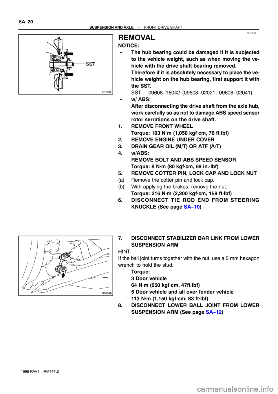
REMOVAL
NOTICE:
�The hub bearing could be damaged if it is subjected
to the vehicle weight, such as when moving the ve-
hicle with the drive shaft bearing removed.
Therefore if it is absolutely necessary to place the ve-
hicle weight on the hub bearing, first support it with
the SST.
SST 09608−16042 (09608−02021, 09608−02041)
�w/ ABS:
After disconnecting the drive shaft from the axle hub,
work carefully so as not to damage ABS speed sensor
rotor serrations on the drive shaft.
1. REMOVE FRONT WHEEL
Torque: 103 N·m (1,050 kgf·cm, 76 ft·lbf)
2. REMOVE ENGINE UNDER COVER
3. DRAIN GEAR OIL (M/T) OR ATF (A/T)
4. w/ABS:
REMOVE BOLT AND ABS SPEED SENSOR
Torque: 8 N·m (80 kgf·cm, 69 in.·lbf)
5. REMOVE COTTER PIN, LOCK CAP AND LOCK NUT
(a) Remove the cotter pin and lock cap.
(b) With applying the brakes, remove the nut.
Torque: 216 N·m (2,200 kgf·cm, 159 ft·lbf)
6. D I S C O N N E C T T I E R O D E N D F R O M S T E E R I N G
KNUCKLE (See page SA−10)
7. DISCONNECT STABILIZER BAR LINK FROM LOWER
SUSPENSION ARM
HINT:
If the ball joint turns together with the nut, use a 5 mm hexagon
wrench to hold the stud.
Torque:
3 Door vehicle
64 N·m (650 kgf·cm, 47ft·lbf)
5 Door vehicle and all over fender vehicle
113 N·m (1,150 kgf·cm, 83 ft·lbf)
8. DISCONNECT LOWER BALL JOINT FROM LOWER
SUSPENSION ARM (See page SA−12)
Page 1147 of 1354
SA0TL−03
R10850
R10823
− SUSPENSION AND AXLEFRONT SHOCK ABSORBER
SA−33
1996 RAV4 (RM447U)
REMOVAL
1. REMOVE FRONT WHEEL
Torque: 103 N·m (1,050 kgf·cm, 76 ft·lbf)
2. DISCONNECT FLEXIBLE HOSE AND ABS SPEED
SENSOR WIRE HARNESS (w/ ABS) FROM SHOCK
ABSORBER
Remove the 2 bolts and disconnect the flexible hose and ABS
speed sensor wire harness.
Torque:
Flexible hose: 19 N·m (192 kgf·cm, 14 ft·lbf)
ABS wire harness: 5 N·m (55 kgf·cm, 48 in.·lbf)
3. DISCONNECT SHOCK ABSORBER FROM STEERING
KNUCKLE
Torque: 158 N·m (1,610 kgf·cm, 117 ft·lbf)
HINT:
At the time of installation, please refer to the following item.
Coat the nut’s threads with engine oil.
4. REMOVE SHOCK ABSORBER WITH COIL SPRING
Remove the 3 nuts, suspension support No.2 and shock ab-
sorber with the coil spring.
Torque: 80 N·m (820 kgf·cm, 59 ft·lbf)
Page 1153 of 1354
SA0TR−03
Z19330
23 Door vehicle
Stabilizer Bar LinkStabilizer
BarPower Steering Gear Assembly
Bracket
No.1
Bushing
Bushing
Clamp
(A/T Only)
Front Suspension
Crossmember
Center MemberLower Suspension
Arm Bracket
Cushion
Retainer
Lower Suspension Arm
LH Engine Cover
29 (300, 22)
29 (300, 22)
113 (1,150, 83)
8.3 (85, 74 in.·lbf)
112 (1,140, 82)
172 (1,750, 126)
206 (2,100, 152)
127 (1,300, 94)
137 (1,400, 101)
28 (290, 21)
�
�N·m (kgf·cm, ft·lbf)
Non−reusable part: Specified torque
X7
Clamp �137 (1,400, 101)
64 (650, 47)
113 (1,150, 83)5 Door vehicle
− SUSPENSION AND AXLEFRONT LOWER SUSPENSION ARM
SA−39
1996 RAV4 (RM447U)
FRONT LOWER SUSPENSION ARM
COMPONENTS
Page 1154 of 1354

SA0TS−03
R10828
A
A B
R10829
W01708
SA−40
− SUSPENSION AND AXLEFRONT LOWER SUSPENSION ARM
1996 RAV4 (RM447U)
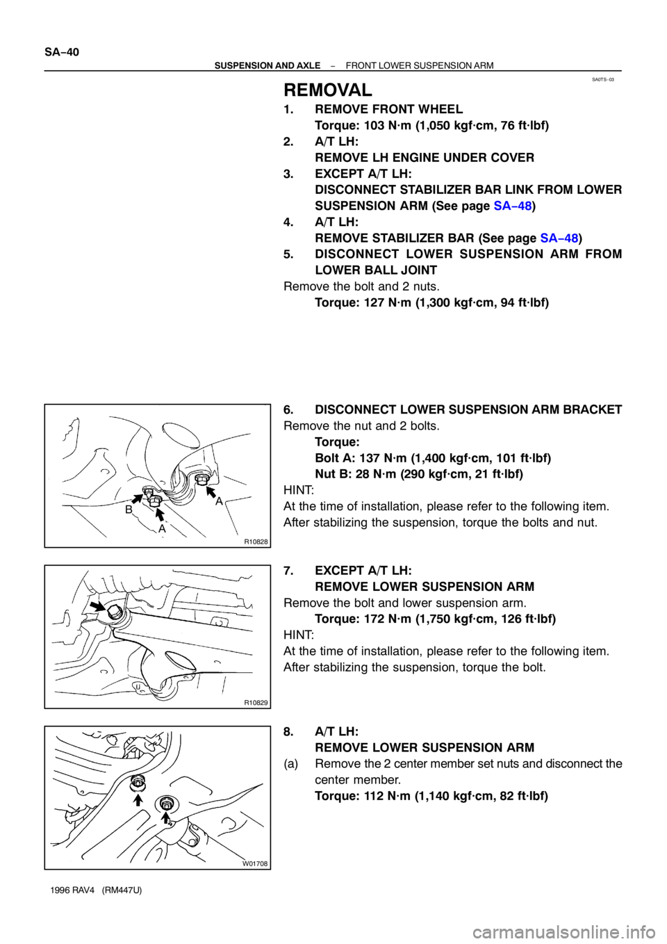
REMOVAL
1. REMOVE FRONT WHEEL
Torque: 103 N·m (1,050 kgf·cm, 76 ft·lbf)
2. A/T LH:
REMOVE LH ENGINE UNDER COVER
3. EXCEPT A/T LH:
DISCONNECT STABILIZER BAR LINK FROM LOWER
SUSPENSION ARM (See page SA−48)
4. A/T LH:
REMOVE STABILIZER BAR (See page SA−48)
5. DISCONNECT LOWER SUSPENSION ARM FROM
LOWER BALL JOINT
Remove the bolt and 2 nuts.
Torque: 127 N·m (1,300 kgf·cm, 94 ft·lbf)
6. DISCONNECT LOWER SUSPENSION ARM BRACKET
Remove the nut and 2 bolts.
Torque:
Bolt A: 137 N·m (1,400 kgf·cm, 101 ft·lbf)
Nut B: 28 N·m (290 kgf·cm, 21 ft·lbf)
HINT:
At the time of installation, please refer to the following item.
After stabilizing the suspension, torque the bolts and nut.
7. EXCEPT A/T LH:
REMOVE LOWER SUSPENSION ARM
Remove the bolt and lower suspension arm.
Torque: 172 N·m (1,750 kgf·cm, 126 ft·lbf)
HINT:
At the time of installation, please refer to the following item.
After stabilizing the suspension, torque the bolt.
8. A/T LH:
REMOVE LOWER SUSPENSION ARM
(a) Remove the 2 center member set nuts and disconnect the
center member.
Torque: 112 N·m (1,140 kgf·cm, 82 ft·lbf)
Page 1161 of 1354
SA0TY−03
Z19330
23 Door vehicle
Stabilizer Bar LinkStabilizer
BarPower Steering Gear Assembly
Bracket
No.1
Bushing
Bushing
Clamp
(A/T Only)
Front Suspension
Crossmember
Center MemberLower Suspension
Arm Bracket
Cushion
Retainer
Lower Suspension Arm
LH Engine Cover
29 (300, 22)
29 (300, 22)
113 (1,150, 83)
8.3 (85, 74 in.·lbf)
112 (1,140, 82)
172 (1,750, 126)
206 (2,100, 152)
127 (1,300, 94)
137 (1,400, 101)
28 (290, 21)
�
�N·m (kgf·cm, ft·lbf)
Non−reusable part: Specified torque
X7
Clamp �137 (1,400, 101)
64 (650, 47)
113 (1,150, 83)5 Door vehicle
− SUSPENSION AND AXLEFRONT STABILIZER BAR
SA−47
1996 RAV4 (RM447U)
FRONT STABILIZER BAR
COMPONENTS
Page 1215 of 1354

SF0Q4−03
− SFISFI SYSTEM
SF−1
1996 RAV4 (RM447U)
SFI SYSTEM
PRECAUTION
1. BEFORE WORKING ON THE FUEL SYSTEM, DISCON-
NECT THE NEGATIVE (−) TERMINAL CABLE FROM
THE BATTERY
HINT:
Any diagnostic trouble code retained by the computer will be
erased when the negative (−) terminal cable is removed.
Therefore, if necessary, read the diagnosis before removing the
terminal.
2. DO NOT SMOKE OR WORK NEAR AN OPEN FLAME
WHEN WORKING ON THE FUEL SYSTEM
3. KEEP GASOLINE AWAY FROM RUBBER OR LEATH-
ER PARTS
4. MAINTENANCE PRECAUTIONS
(a) In event of engine misfire, these precautions should be
taken.
(1) Check proper connection to battery terminals, etc.
(2) After repair work, check that the ignition coil termi-
nals and all other ignition system lines are recon-
nected securely.
(3) When cleaning the engine compartment, be espe-
cially careful to protect the electrical system from
water.
(b) Precautions when handling oxygen sensor.
(1) Do not allow oxygen sensor to drop or hit against an
object.
(2) Do not allow the sensor to come into contact with
water.
5. IF VEHICLE IS EQUIPPED WITH MOBILE RADIO SYS-
TEM (HAM, CB, ETC.)
If the vehicle is equipped with a mobile communication system,
refer to the precaution in the IN section.
6. AIR INDUCTION SYSTEM
(a) Separation of the engine oil dipstick, oil filler cap, PCV
hose, etc. may cause the engine to run out of tune.
(b) Disconnection, looseness or cracks in the parts of the air
induction system between the throttle body and cylinder
head will allow air suction and cause the engine to run out
of tune.
7. ELECTRONIC CONTROL SYSTEM
(a) Before removing SFI wiring connectors, terminals, etc.,
first disconnect the power by either turning the ignition
switch to LOCK or disconnecting the negative (−) terminal
cable from the battery.
HINT:
Always check the diagnostic trouble code before disconnecting
the negative (−) terminal cable from the battery.