Page 1238 of 1354
S01941
S01953
Install
Air Hose
S01948
No.1
No.2
No.3
No.4
Gray
Brown SF−24
− SFIINJECTOR
1996 RAV4 (RM447U)
(f) Tighten the 2 bolts holding the delivery pipe to the cylinder
head.
Torque: 13 N·m (130 kgf·cm, 9 ft·lbf)
(g) Install the air hose for the air assist system to the intake
manifold port.
(h) Connect the fuel inlet hose to the fuel filter with 2 new gas-
kets and the union bolt.
Torque: 29 N·m (300 kgf·cm, 22 ft·lbf)
3. INSTALL ENGINE COMPARTMENT R/B NO.2
4. INSTALL EGR VALVE AND PIPE
HINT:
Place a new gasket on the intake manifold.
Torque:
Nut:
13 N·m (130 kgf·cm, 9 ft·lbf)
Union nut:
59 N·m (600 kgf·cm, 43 ft·lbf)
5. CONNECT ENGINE WIRE TO INTAKE MANIFOLD
HINT:
The No.1 and No.3 injector connectors are brown, and the No.2
and No.4 injector connectors are gray.
6. CONNECT THROTTLE BODY TO INTAKE MANIFOLD
7. INSTALL CYLINDER HEAD COVER (See page EM−55
)
8. INSTALL AIR CLEANER ASSEMBLY
9. INSTALL DISTORIBUTOR (See page IG−13)
Page 1241 of 1354

THROTTLE BODY
ON−VEHICLE INSPECTION
1. INSP")
S01898
SF0QO−03
S01946
P
E
R
S00037
Ohmmeter
Throttle Position Sensor
VC
VTA
E2
S01901
Disconnect
Plug
− SFITHROTTLE BODY
SF−27
1996 RAV4 (RM447U)
THROTTLE BODY
ON−VEHICLE INSPECTION
1. INSPECT THROTTLE BODY
(a) Check that the throttle linkage moves smoothly.
(b) Check the vacuum at each port.
�Start the engine.
�Check the vacuum with your finger.
Port nameAt idleOther than idle
PNo vacuumVacuum
ENo vacuumVacuum
RNo vacuumNo vacuum
2. INSPECT THROTTLE POSITION SENSOR
(a) Apply vacuum to the throttle opener.
(b) Disconnect the sensor connector.
(c) Using an ohmmeter, measure the resistance between
each terminal.
Clearance between
lever and stop screwBetween
terminalsResistance
0 mm (0 in.)VTA − E20.2 − 5.7 kΩ
Throttle valve fully
openVTA − E22.0 − 10.2 kΩ
−VC − E22.5 − 5.9 kΩ
(d) Reconnect the sensor connector.
3. INSPECT AND ADJUST THROTTLE OPENER
4. WARM UP ENGINE
Allow the engine to warm up to normal operating temperature.
5. CHECK IDLE SPEED
Idle speed: 700 ± 50 rpm
6. CHECK AND ADJUST THROTTLE OPENER SETTING
SPEED
(a) Disconnect the vacuum hose from the throttle opener,
and plug the hose end.
(b) Maintain the engine at 2,500 rpm.
(c) Release the throttle valve.
(d) Check that the throttle opener is set.
Throttle opener setting speed:
1,300 − 1,500 rpm (w/ cooling fan OFF)
Page 1244 of 1354
 (3)
(2)
(1)
S01907
A
B
Protrusion
(Bolt: Type A)
(Nut: Type B)B A
S01902
(1)
(3)(2) SF−30
− SFITHROTTLE BODY
1996 RAV4 (RM447U)
REMOVAL
1. DRAIN ENGINE COOLANT
2. A/T:
DISC")
SF0QQ−03
S01905
(4) (3)
(2)
(1)
S01907
A
B
Protrusion
(Bolt: Type A)
(Nut: Type B)B A
S01902
(1)
(3)(2) SF−30
− SFITHROTTLE BODY
1996 RAV4 (RM447U)
REMOVAL
1. DRAIN ENGINE COOLANT
2. A/T:
DISCONNECT THROTTLE CABLE FROM THROTTLE
BODY
3. DISCONNECT ACCELERATOR CABLE FROM
THROTTLE BODY
4. REMOVE AIR CLEANER CAP ASSEMBLY (See page
ST−4)
5. REMOVE THROTTLE BODY
(a) Disconnect the throttle position sensor connector.
(b) Disconnect the IAC valve connector.
(c) Disconnect these hoses from the throttle body:
(1) PCV hose from air tube
(2) Vacuum hose from port ”R” of EGR vacuum modu-
lator
(3) Vacuum hose from port ”P” of EGR vacuum modu-
lator
(4) EVAP hose from chacoal canister
(d) Remove the 4 bolts (Type A) or the 2 bolts, 2 nuts (Type
B) and gasket, and diaconnect the throttle body from the
intake manifold.
Torque: 19 N·m (195 kgf·cm, 14 ft·lbf)
HINT:
At the time of installation, plaese refer to the following items.
�Place a new gasket on the intake chamber, facing the pro-
trusion downward.
�Each bolt is indicated in the illustration (Type A).
Bolt length:
A: 40 mm (1.57 in.)
B: 55 mm (2.17 in.)
(e) Disconnect these hoses from the throttle body:
(1) Water bypass hose from water outlet
(2) Water bypass hose from water bypass pipe
(3) Air hose from intake manifold
Page 1248 of 1354
 VALVE
1996 RAV4 (RM447U)
IDLE AIR CONTROL (IAC) VALVE
ON−VEHICLE INSPECTION
1. INSPECT I")
SF0QT−02
S01261
SST DLC1
E1 TE1
S01904
RSC
RSO+B
Ohmmeter
IAC Valve SF−34
− SFIIDLE AIR CONTROL (IAC) VALVE
1996 RAV4 (RM447U)
IDLE AIR CONTROL (IAC) VALVE
ON−VEHICLE INSPECTION
1. INSPECT IAC VALVE OPERATION
(a) Initial conditions:
�Engine at normal operating temperature
�Idle speed check correctly
�Transmission in neutral position
(b) Using SST, connect terminals TE1 and E1 of the DLC1.
SST 09843−18020
(c) Maintain engine speed in the range between 900 − 1,300
rpm for 5 seconds. Check that it returns to idle speed.
If the engine speed operation is not as specified, check the IAC
valve, wiring and ECM.
(d) Remove the SST.
SST 09843−18020
2. INSPECT IAC VALVE RESISTANCE
NOTICE:
”Cold” and ”Hot” in these sentences express the tempera-
ture of the coils themselves. ”Cold” is from −10°C (14°F) to
50°C (122°F) and ”Hot” is from 50°C (122°F) to 100°C
(212°F).
(a) Disconnect the IAC valve connector.
(b) Using an ohmmeter, measure the resistance between ter-
minal +B and other terminals (RSC, RSO).
Resistance:
Cold: 17.0 − 24.5 Ω
Hot: 21.5 − 28.5 Ω
If resistance is not as specified, replace the IAC valve.
(c) Reconnect the IAC valve connector.
Page 1259 of 1354
SF0R7−01
S01930
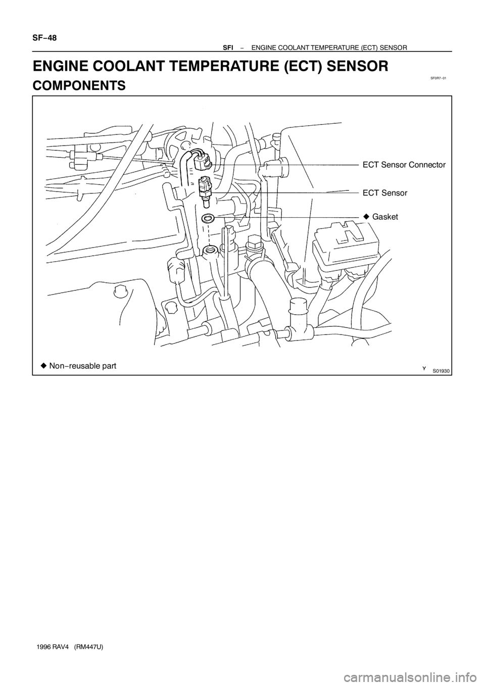
ECT Sensor Connector
ECT Sensor
� Gasket
� Non−reusable part SF−48
− SFIENGINE COOLANT TEMPERATURE (ECT) SENSOR
1996 RAV4 (RM447U)
ENGINE COOLANT TEMPERATURE (ECT) SENSOR
COMPONENTS
Page 1260 of 1354
SF0R8−01
S01196S01699
Z17274
35 1020 30
TEMPERATURE°C (°F) Acceptable
RESISTANCE kΩ
2
1
0.5
0.3
0.2
0.1
−20 0
2040 60
(32)(68)(104)(140)(176)(212)
(−4)100 80
Ohmmeter
− SFIENGINE COOLANT TEMPERATURE (ECT) SENSOR
SF−49
1996 RAV4 (RM447U)
INSPECTION
1. DRAIN ENGINE COOLANT
2. REMOVE ECT SENSOR
3. INSPECT ECT SENSOR RESISTANCE
Using an ohmmeter, measure the resistance between the ter-
minals.
Resistance: Refer to the graph
If the resistance is not as specified, replace the sensor.
4. REINSTALL ECT SENSOR
Install a new gasket to the ECT sensor.
Torque: 25 N·m (250 kgf·cm, 18 ft·lbf)
5. FILL WITH ENGINE COOLANT
Page 1268 of 1354
SF0RG−02
S01838
2WD
SST
P01630
Ohmmeter
− SFIKNOCK SENSOR
SF−57
1996 RAV4 (RM447U)
INSPECTION
1. 4WD:
REMOVE ENGINE AND TRANSAXLE ASSEMBLY (See
page EM−68)
2. REMOVE KNOCK SENSOR
(a) Disconnect the knock sensor connector.
(b) Using SST, remove the knock sensor.
SST 09816−30010
Torque: 44 N·m (450 kgf·cm, 33 ft·lbf)
3. INSPECT KNOCK SENSOR
Using an ohmmeter, check that there is no continuity between
the terminal and body.
If there is continuity, replace the sensor.
4. REINSTALL KNOCK SENSOR
Installation is in the reverse order of removal.
5. 4WD:
REINSTALL ENGINE AND TRANSAXLE ASSEMBLY
(See page EM−74)
Page 1272 of 1354
SF0RK−01
S01842
Floor Carpet
Center Cover LH
BracketECM Connector
ECM Cover
ECM ECM Assembly
Bracket
Bracket
− SFIENGINE CONTROL MODULE (ECM)
SF−61
1996 RAV4 (RM447U)
ENGINE CONTROL MODULE (ECM)
COMPONENTS

(f) Tighten the 2 bolts holding the delivery pipe to the cylinder
head.
Torque: 13 N·")
 Acceptable
RESISTANCE kΩ
2
1
0.5
0.3
0.2
0.1
−20 0
2040 60
(32)(68)(104)(140)(176)(212)
(−4)100 80
Ohmmeter
− SFIENGINE COOLANT TE")

INSPECTION
1. 4WD:
REMOVE ENGINE AND TRANSAXLE ASSEMBLY (See
page EM−68)
2. REMOVE KNOCK SENSOR
(a) Disconn")

SF−61
1996 RAV4 (RM447U)
ENGINE CONTROL MODULE (EC")