Page 282 of 1354
CL04H−02
Q11030
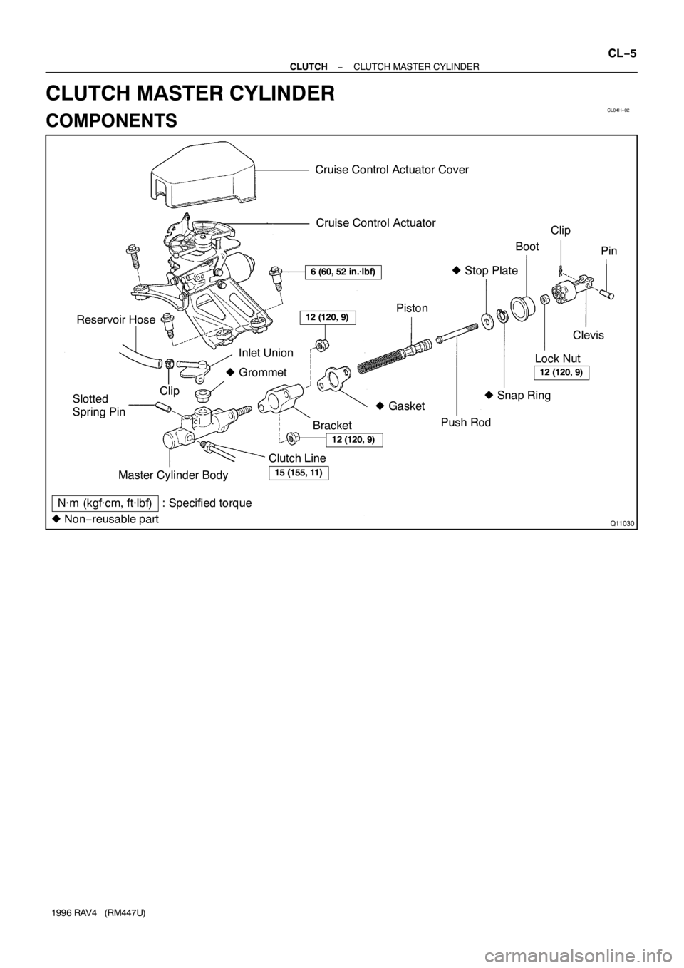
Cruise Control Actuator Cover
N·m (kgf·cm, ft·lbf) : Specified torqueMaster Cylinder Body Reservoir Hose
Slotted
Spring PinInlet Union
� Grommet
Clutch Line
BracketBootClip
Clevis
Lock Nut
� Gasket Clip
� Snap Ring � Stop Plate
Piston
� Non−reusable part
6 (60, 52 in.·lbf)
12 (120, 9)
15 (155, 11)
12 (120, 9)
Cruise Control Actuator
Pin
Push Rod
12 (120, 9)
− CLUTCHCLUTCH MASTER CYLINDER
CL−5
1996 RAV4 (RM447U)
CLUTCH MASTER CYLINDER
COMPONENTS
Page 283 of 1354
CL04I−02
Q08876
Q08877SST CL−6
− CLUTCHCLUTCH MASTER CYLINDER
1996 RAV4 (RM447U)
REMOVAL
1. w/ Cruise Control System:
REMOVE CRUISE CONTROL ACTUATOR COVER
2. w/ Cruise Control System:
REMOVE CRUISE CONTROL ACTUATOR
Remove the 3 bolts.
Torque: 6 N·m (60 kgf·cm, 52 in.·lbf)
3. DRAW OUT FLUID WITH SYRINGE
4. DISCONNECT CLUTCH LINE
Using SST, disconnect the clutch line. Use a container to catch
the fluid.
SST 09023−00100
Torque: 15 N·m (155 kgf·cm, 11 ft·lbf)
5. DISCONNECT RESERVOIR HOSE FROM MASTER
CYLINDER
Using pliers, disconnect the clip and reservoir hose.
6. REMOVE CLIP AND PIN
7. REMOVE 2 MOUNTING NUTS AND PULL OUT MAS-
TER CYLINDER
Torque: 12 N·m (120 kgf·cm, 9 ft·lbf)
Page 339 of 1354

− DIAGNOSTICSENGINE
DI−19
1996 RAV4 (RM447U) FC (E6−14) − E1 (E4−14)
G−R ↔ BRIG switch ON9 ∼ 14
EGR (E4−23) − E1 (E4−14)B−W ↔ BRIG switch ON0 ∼ 3
ISCC (E4−9) − E1 (E4−14)B−Y ↔ BRIG switch ON
Disconnect E4 of ECM connector9 ∼ 14
ISCO (E4−10) − E1 (E4−14)B−L ↔ BRIG switch ON
Disconnect E4 of ECM connector9 ∼ 14
OX1 (E5−6) − E1 (E4−14)B ↔ BRMaintain engine speed at 2,500 rpm for 2 mins. after
warning up.Pulse generation
OX2 (E5−5) − E1 (E4−14)B ↔ BRMaintain engine speed at 2,500 rpm for 2 mins. after
warning up.Pulse generation
KNK (E5−10) − E1 (E4−14)B ↔ BRIdlingPulse generation
(See page DI−56)
* NSW (E6−22) − E1 (E4−14)B−W ↔ BR
IG switch ON
Other shift position in ”P” , ”N” position9 ∼ 14
IG switch ON
Shift position in ”P” , ”N” position0 ∼ 3.0
SPD (E6−9) − E1 (E4−14)V−W ↔ BRIG switch ON
Rotate driver wheel slowly.Pulse generation
(See page DI−94)
TE1 (E5−15) − E1 (E4−14)L−W ↔ BRIG switch ON9 ∼ 14
W (E6−5) − E1 (E4−14)G−R ↔ BRIdling9 ∼ 14
IG switch ONBelow 3.0
AC (E6−10) − E1 (E4−14)Y−G ↔ BRIdling, A/C switch ONBelow 2.0
Idling, A/C switch OFF9 ∼ 14
ACT (E6−21) − E1 (E4−14)R−Y ↔ BRIdling, A/C switch ON9 ∼ 14
Idling, A/C switch OFFBelow 2.0
* OD2 (E6−7) − E1 (E4−14)LG ↔ BRIG switch ON, O/D main switch pushed out9 ∼ 14
IG switch ON, O/D main switch pushed in0 ∼ 3
* OD1 (E6−20) − E1 (E4−14)Y−B ↔ BRIG switch ON, Cruise control ECU no request O/D cut9 ∼ 14
IG switch ON, Cruise control ECU request O/D cut0 ∼ 3
EVP (E4−22) − E1 (E4−14)P ↔ BRIG switch ON9 ∼ 14
TPC (E5−8) − E1 (E4−14)R−W ↔ BRIG switch ON9 ∼ 14
PTNK (E5−7) − E2 (E5−9)L−Y ↔ BR
IG switch ON, Disconnect vacuum hose from vapor
pressure sensor2.9 ∼ 3.7
Apply vacuum
(4.0 kPa, 30 mmHg, 1.18 in. Hg)
(less than 66.7 kPa, 500 mmHg, 19.7 in. Hg)
Below 0.5
ELS (E6−17) − E1 (E4−14)B ↔ BRDefogger switch and taillight switch ON7.5 ∼ 14
Defogger switch and taillight switch OFF0 ∼ 1.5
SDL (E6−16) − E1 (E4−14)W ↔ BRDuring transmissionPules generation
*: A/T only
Page 355 of 1354
P25426
Throttle Position Sensor
4
E5
3
2L
1
BR L−R Y5V
VC
VTA
E2
E1 From Cruise
Control ECU1
11
9 E5
E5ECM
FI7052
− DIAGNOSTICSENGINE
DI−35
1996 RAV4 (RM447U)
WIRING DIAGRAM
INSPECTION PROCEDURE
HINT:
If DTC P0105” (Manifold Absolute Pressure / Barometric Pressure Circuit Malfunction), ”P0110” (Intake Air
Temp. Circuit Malfunction), ”P0115” (Engine Coolant Temp. Circuit Malfunction), ”P0120” (Throttle / Pedal
Position Sensor / Switch ”A” Circuit Malfunction) are output simultaneously, E2 (sensor ground) may be
open.
1 Connect OBDII scan tool or TOYOTA hand−held tester and read the throttle valve
opening percentage.
PREPARATION:
(a) Connect the OBDII scan tool or TOYOTA hand−held tester to the DLC3.
(b) Turn ignition switch ON and OBDII scan tool or TOYOTA hand−held tester main switch ON.
CHECK:
Read the throttle valve opening percentage.
OK:
Throttle valveThrottle valve opening position
expressed as percentage
Fully openApprox. 70 %
Fully closedApprox. 10 %
Page 451 of 1354
− DIAGNOSTICSAUTOMATIC TRANSAXLE (A241E)
DI−131
1996 RAV4 (RM447U)
4. CHECK FOR INTERMITTENT PROBLEMS
TOYOTA hand−held tester only:
By putting the vehicle’s ECM in check mode, 1 trip detection logic is possible instead of 2 trip detection logic
and sensitivity to detect open circuits is increased. This makes it easier to detect intermittent problems.
(1) Clear the DTCs (See step 3).
(2) Set the check mode (See step 3).
(3) Do simulation test (See page IN−20).
(4) Check the connector connection and terminal (See page IN−30).
(5) Visual check and contact pressure (See page IN−20).
(6) Handle the connector (See page IN−20).
5. PROBLEM SYMPTOM CONFIRMATION
Taking into consideration the results of the customer problem analysis, try to reproduce the symptoms of the
trouble. If the problem is that the transaxle does not up−shift, down−shift, or the shift point is too high or too
low, conduct the following road test to confirm the automatic shift schedule and simulate the problem symp-
toms.
6. ROAD TEST
NOTICE:
Do the test at normal operating ATF temperature 50 − 80°C (122 − 176°F).
(a) D position test.
Shift into the D position, keep the accelerator pedal constant at the full throttle valve opening position
and check the following points:
(1) Check up− shift operation.
Check that 1 → 2, 2 → 3 and 3 → O/D up−shift takes place, at the shift point shown in the automat-
ic shift schedule (See page SS−32).
HINT:
�O/D Gear Up−shift Prohibition Control:
Engine coolant temperature is 50°C (122°F) or less.
If there is a 10km/h (6 mph) difference between the set cruise control speed and vehicle speed.
O/D main switch is pushed ON (During the O/D OFF indicator light lights up.).
�O/D Gear Lock−up Prohibition Control:
Brake pedal is depressed.
Engine coolant temperature is 50°C (122°F) or less.
(2) Check for shift shock and slip.
Check for shock and slip at the 1 → 2, 2 → 3 and 3 → O/D up−shifts.
(3) Check for abnormal noise and vibration.
Run at the D position lock−up or O/D gear and check for abnormal noise and vibration.
HINT:
The check for the cause of abnormal noise and vibration must be performed very thoroughly as it could also
be due to loss of balance in the torque converter clutch, etc.
(4) Check kick−down operation.
While running in the D position, 2nd, 3rd and O/D gears, check that the possible kick−down ve-
hicle speed limits for 2 → 1, 3 → 2 and O/D → 3 kick−downs conform to those indicated on the
automatic shift schedule (See page SS−32).
(5) Check abnormal shock and slip at kick−down.
(6) Check the lock−up mechanism.
�Drive in the D position, O/D gear, at a steady speed (lock−up ON) of about 75 km/h (47
mph).
�Lightly depress the accelerator pedal and check that the RPM does not change abruptly.
If there is a big jump in RPM, there is no lock−up.
Page 460 of 1354

DI40E−02
Z16062
ECM Terminals
E4E5
E6 DI−140
− DIAGNOSTICSAUTOMATIC TRANSAXLE (A241E)
1996 RAV4 (RM447U)
TERMINALS OF ECM
Symbols (Terminal No.)Wiring ColorConditionSTD Voltage (V)
SPD (E6−9) − E1 (E4−14)V−W − BRDisconnect cruise control connector and IG ON
Turn one front wheel slowlyPulse signal is output
Below 1 ↔ 4 − 6
S1 (E4−2) − E1 (E4−14)P−B − BR
IG OFF Disconnect ECM connector11 − 15 Ω
IG ON10 − 14
1st or 2nd gear10 − 14
3rd or O/D gearBelow 1
S2 (E4−15) − E1 (E4−14)P − BR
IG OFF Disconnect ECM connector11 − 15 Ω
IG ONBelow 1
2nd or 3rd gear10 − 14
1st or O/D gearBelow 1
SL (E4−1) − E1 (E4− 4)Y−B − BR
IG OFF Disconnect ECM connector11 − 15 Ω
IG ONBelow 1
Vehicle driving under look−up position10 − 14
OD1 (E6−20) − E1 (E4−14)Y−B − BRIG ON4 − 6
OD2 (E6−7) − E1 (E4−14)LG − BRO/D main switch ON (O/D ON)10 − 14
O/D main switch OFF (O/D OFF)Below 1
L (E6−19) − E1 (E4−14)LG − BRIG ON Shift lever L position10 − 14
IG ON Shift lever other than L positionBelow 1
R (E6−8) − E1 (E4−14)R−B − BRIG ON Shift lever R position10 − 14
IG ON Shift lever other than R positionBelow 1
2 (E−18)− E1 (E4−14)LG−R − BRIG ON Shift lever 2 position10 − 14
IG ON Shift lever other than R positionBelow 1
NSW (E6−22) − E1 (E4−14)B−W − BRIG ON Shift lever P or N positionBelow 1
IG ON Shift lever other than P or N position10 − 14
B/K (E6−4) − E1 (E4−14)G−W − BRIG ON Brake papel is depressed7.5 − 14
IG ON Brake papel is releasedBelow 1
P (E6−15) − E1 (E4−14)R−G − BRPWR pattern7.5 − 14
NORM patternBelow 1
Page 468 of 1354
Q06970
Shift Solenoid
Valve No. 1Transaxle
Shift Solenoid
Valve No. 2
To Cruise Control ECUS2ECM
P−B 3
E1
E1
E4 E4
1
152
PB+ B+
S1
Q08088
S1
S2
DI−148
− DIAGNOSTICSAUTOMATIC TRANSAXLE (A241E)
1996 RAV4 (RM447U)
WIRING DIAGRAM
INSPECTION PROCEDURE
1 Measure resistance between terminal S1 or S2 of ECM and body ground.
PREPARATION:
Disconnect the connector from the ECM.
CHECK:
Measure the resistance between terminal S1 or S2 of the ECM
and body ground.
OK:
Resistance: 11 − 15 Ω
OK Check and replace ECM.
NG
Page 486 of 1354
Q05352
Cruise Control ECU
C16
ECM
4 − 6 V
9
ODOD1
Y−B20
E6
D02210
ON
OD1
DI−166
− DIAGNOSTICSAUTOMATIC TRANSAXLE (A241E)
1996 RAV4 (RM447U)
O/D Cancel Signal Circuit
CIRCUIT DESCRIPTION
While driving uphill with cruise control activated, in order to minimize gear shifting and provide smooth cruis-
ing, O/D may be prohibited temporarily under some conditions.
The cruise control ECU sends O/D cur signals to the ECM as necessary and the ECM cancels O/D shifting
until these signals are discontinued.
WIRING DIAGRAM
INSPECTION PROCEDURE
1 Check voltage between terminal OD1 of ECM and body ground.
PREPARATION:
Turn the ignition switch ON.
CHECK:
Measure the voltage between terminal OD1 of the ECM and
body ground.
OK:
Voltage: 4 − 6 V
OK Proceed next circuit inspection shown on prob-
lem symptoms table (See page DI−141).
NG
DI40O−01