Page 420 of 1354

S07638
IG1
1H 1DI4I4
E4
E43 20
EA17
IG111
2221
20 8
1412
67
2
W B−WB−RB−R B−W
B−W
B−W
B−W
L−Y 4
53
2
1 Tr2
Igniter To Tachometer Distributor
BatteryFusible Link BlockR/B No.2
B−R IG Switch 4ECM
IGT
IGF5V
Tr1
AM2B
B−Y
Ignition Coil
J/B No.1
MAIN DI−100
− DIAGNOSTICSENGINE
1996 RAV4 (RM447U)
DTC P1300 Igniter Circuit Malfunction
CIRCUIT DESCRIPTION
This ECM determines the ignition timing, turns on Tr1 at a predetermined angle (°CA) before the desired
ignition timing and outputs an ignition signal (IGT) ”1” to the igniter.
Since the width of the IGT signal is constant, the dwell angle control circuit in the igniter determines the time
the control circuit starts primary current flow to the ignition coil based on the engine rpm and ignition timing
one revolution ago, that is, the time the Tr
2 turns on.
When it reaches the ignition timing, the ECM turns Tr
1 off and outputs the IGT signal ”O”.
This turns Tr
2 off, interrupting the primary current flow and generating a high voltage in the secondary coil
which causes the spark plug to spark. Also, by the counter electromotive force generated when the primary
current is interrupted, the igniter sends an ignition confirmation signal (IGF) to the ECM.
The ECM stops fuel injection as a fail safe function when the IGF signal is not input to the ECM.
DTC No.DTC Detecting ConditionTrouble Area
P1300No IGF signal to ECM for 8 consecutive IGT signals during
engine running.�Open or short in IGF or IGT circuit from igniter to ECM
�Igniter
�ECM
WIRING DIAGRAM
DI401−01
Page 423 of 1354

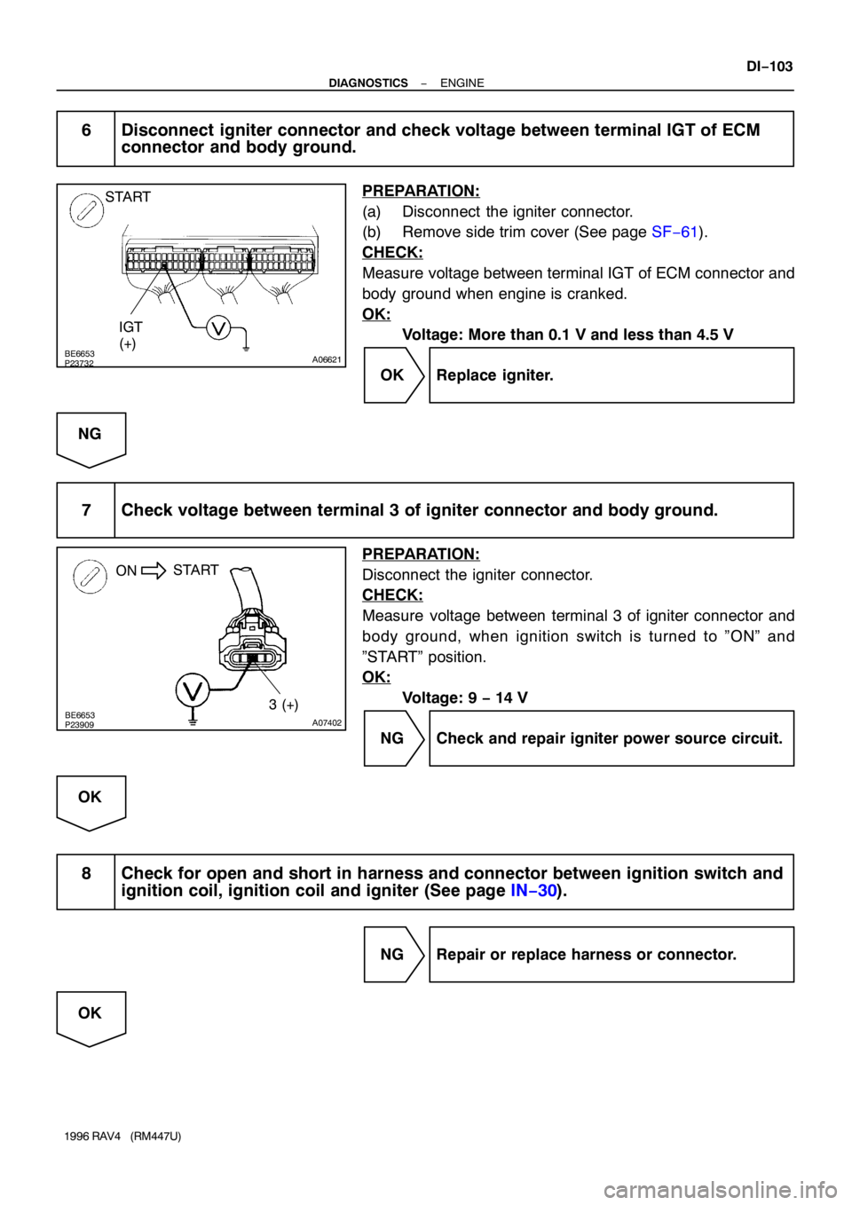
BE6653P23732A06621
START
IGT
(+)
BE6653P23909A07402
ON
3 (+) START
− DIAGNOSTICSENGINE
DI−103
1996 RAV4 (RM447U)
6 Disconnect igniter connector and check voltage between terminal IGT of ECM
connector and body ground.
PREPARATION:
(a) Disconnect the igniter connector.
(b) Remove side trim cover (See page SF−61).
CHECK:
Measure voltage between terminal IGT of ECM connector and
body ground when engine is cranked.
OK:
Voltage: More than 0.1 V and less than 4.5 V
OK Replace igniter.
NG
7 Check voltage between terminal 3 of igniter connector and body ground.
PREPARATION:
Disconnect the igniter connector.
CHECK:
Measure voltage between terminal 3 of igniter connector and
body ground, when ignition switch is turned to ”ON” and
”START” position.
OK:
Voltage: 9 − 14 V
NG Check and repair igniter power source circuit.
OK
8 Check for open and short in harness and connector between ignition switch and
ignition coil, ignition coil and igniter (See page IN−30).
NG Repair or replace harness or connector.
OK
Page 424 of 1354
DI−104
− DIAGNOSTICSENGINE
1996 RAV4 (RM447U)
9 Check ignition coil (See page IG−1).
NG Replace ignition coil.
OK
Replace igniter.
Page 433 of 1354
S02409
2
227
26
66
62
9
7
8
92
1 1E1D
1J
1E EA1
IG1
EA
EC A
AA
A
W
R/B No.2R−W
11
17
1621
20
10 11J2
Junction
Connector J1
Junction
ConnectorECM
B−R
Fusible
Link
Block
MAIN
Fuse BlockIGN IG
Switch
B6
B−R
B−R B−R1
2 3
5
EA1
IG1
E6
E4+B
E1 12
BR14 B−R R/B No.6
EFI Main Relay
J/B
No.1
BatteryB−R
EFI
AM1
B−O
B−O B−OW−B
W−BBR
− DIAGNOSTICSENGINE
DI−11 3
1996 RAV4 (RM447U)
ECM Power Source Circuit
CIRCUIT DESCRIPTION
When the ignition switch is turned ON, battery positive voltage is applied to the coil, closing the contacts of
the EFI relay and supplying power to the terminals +B of the ECM.
WIRING DIAGRAM
DI406−01
Page 436 of 1354
S02410
EFI
MAIN No.1
IG Switch AM2
MAIN
FL
BatteryPark/Neutral
Position Switch
(Clutch Start
Switch)EFI Main
RelayCircuit Opening
Relay
Fuel Pump
ECM
FC
Tr
STA
NE� (STA Signal)
(NE Signal) Starter IGN
ST Relay DI−11 6
− DIAGNOSTICSENGINE
1996 RAV4 (RM447U)
Fuel Pump Control Circuit
CIRCUIT DESCRIPTION
In the diagram below, when the engine is cranked, current flows from terminal ST of the ignition switch to
the starter relay coil and also current flows to terminal STA of ECM (STA signal).
When the STA signal and NE signal are input to the ECM, Tr is turned ON, current flows to coil of the circuit
opening relay, the relay switches on, power is supplied to the fuel pump and the fuel pump operates.
While the NE signal is generated (engine running), the ECM keeps Tr ON (circuit opening relay ON) and the
fuel pump also keeps operating.
DI407−02
Page 669 of 1354

EM0EH−03
S01361
Compression
Gauge
− ENGINE MECHANICALCOMPRESSION
EM−3
1996 RAV4 (RM447U)
COMPRESSION
INSPECTION
HINT:
If there is lack of power, excessive oil consumption or poor fuel
economy, measure the compression pressure.
1. WARM UP AND STOP ENGINE
Allow the engine to warm up to normal operating temperature.
2. DISCONNECT DISTRIBUTOR CONNECTOR
3. DISCONNECT HIGH−TENSION CORDS FROM SPARK
PLUGS AND IGNITION COIL
4. REMOVE SPARK PLUGS
5. CHECK CYLINDER COMPRESSION PRESSURE
(a) Insert a compression gauge into the spark plug hole.
(b) Fully open the throttle.
(c) While cranking the engine, measure the compression
pressure.
HINT:
Always use a fully charged battery to obtain engine speed of
250 rpm or more.
(d) Repeat steps (a) through (c) for each cylinder.
NOTICE:
This measurement must be done in as short a time as pos-
sible.
Compression pressure:
1,275 kPa (13.0 kgf/cm
2, 185 psi) or more
Minimum pressure: 932 kPa (9.5 kgf/cm
2, 135 psi)
Difference between each cylinder:
98 kPa (1.0 kgf/cm
2, 14 psi) or less
(e) If the cylinder compression in one or more cylinders is low,
pour a small amount of engine oil into the cylinder through
the spark plug hole and repeat steps (a) through (c) for
cylinders with low compression.
�If adding oil helps the compression, it is likely that
the piston rings and/or cylinder bore are worn or
damaged.
�If pressure stays low, a valve may be sticking or
seating is improper, or there may be leakage past
the gasket.
6. REINSTALL SPARK PLUGS
7. RECONNECT HIGH−TENSION CORDS TO SPARK
PLUGS AND IGNITION COIL
Page 736 of 1354

S01432
S01285
S01347
EM−70
− ENGINE MECHANICALENGINE UNIT
1996 RAV4 (RM447U)
22. DISCONNECT CONNECTORS, CORD, STRAP AND
HOSES
(a) Disconnect the vapor pressure sensor connector.
(b) Disconnect the igniter connector.
(c) Disconnect the ignition coil connector.
(d) Disconnect the noise filter connector.
(e) Disconnect the high−tension cord from the ignition coil.
(f) Disconnect the MAP sensor connector.
(g) Disconnect the MAP sensor vacuum hose from the gas
filter on the intake manifold.
(h) Disconnect the brake booster hose from the intake man-
ifold.
(i) 4WD M/T:
Disconnect the differential lock control solenoid connec-
tor.
(j) Disconnect the ground strap from the cowl.
23. DISCONNECT ENGINE WIRE FROM CABIN
(a) Remove the RH scuff plate.
(b) Remove the RH cowl side trim.
(c) Remove the RH floor carpet center cover.
(d) Disconnect the 2 ECM connectors.
(e) Disconnect the 2 connectors from the connectors on the
bracket.
(f) Disconnect the connector from the J/B No. 4.
(g) Disconnect the wire clamp from the bracket.
(h) Pull out the engine wire from the cabin.
24. REMOVE FRONT EXHAUST PIPE
(a) Using a 14 mm deep socket wrench, remove the 2 bolts
holding the front exhaust pipe to the front TWC.
(b) Remove the 2 bolts and 2 nuts holding the front exhaust
pipe to the TWC w/ pipe.
(c) Remove the front exhaust pipe and 2 gaskets.
25. DISCONNECT A/C COMPRESSOR FROM ENGINE
(a) Disconnect the A/C compressor connector.
(b) Remove the 2 bolts, nut and stud bolt, and disconnect the
A/C compressor from the engine.
HINT:
Suspend the A/C compressor securely.
26. 4WD only:
REMOVE PROPELLER SHAFT (See page PR−3)
27. REMOVE FRONT DRIVE SHAFT (See page SA−20)
28. REMOVE STABILIZER (See page SA−40)
Page 744 of 1354

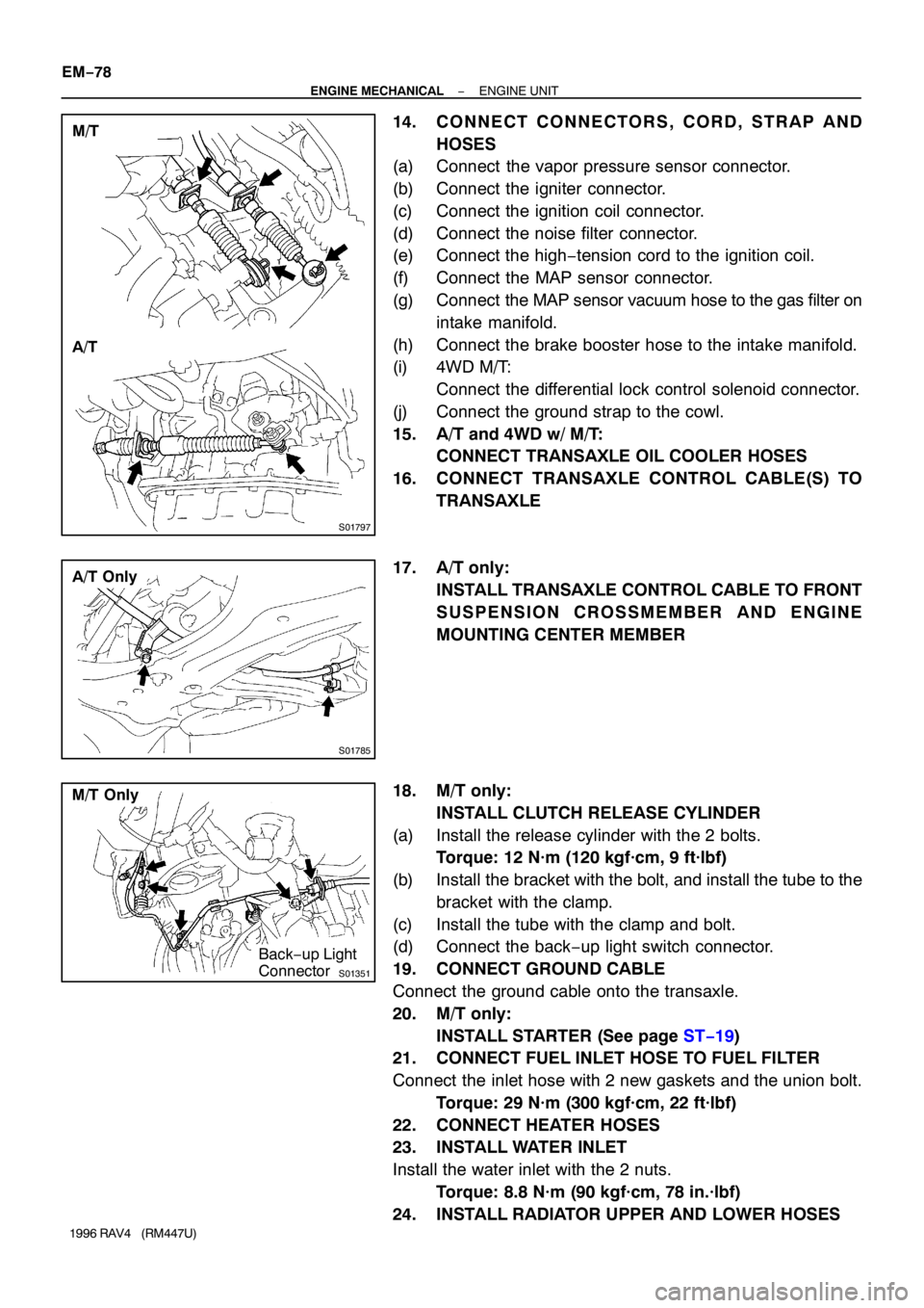
S01797
M/T
A/T
S01785
A/T Only
S01351
M/T Only
Back−up Light
Connector EM−78
− ENGINE MECHANICALENGINE UNIT
1996 RAV4 (RM447U)
14. CONNECT CONNECTORS, CORD, STRAP AND
HOSES
(a) Connect the vapor pressure sensor connector.
(b) Connect the igniter connector.
(c) Connect the ignition coil connector.
(d) Connect the noise filter connector.
(e) Connect the high−tension cord to the ignition coil.
(f) Connect the MAP sensor connector.
(g) Connect the MAP sensor vacuum hose to the gas filter on
intake manifold.
(h) Connect the brake booster hose to the intake manifold.
(i) 4WD M/T:
Connect the differential lock control solenoid connector.
(j) Connect the ground strap to the cowl.
15. A/T and 4WD w/ M/T:
CONNECT TRANSAXLE OIL COOLER HOSES
16. CONNECT TRANSAXLE CONTROL CABLE(S) TO
TRANSAXLE
17. A/T only:
INSTALL TRANSAXLE CONTROL CABLE TO FRONT
SUSPENSION CROSSMEMBER AND ENGINE
MOUNTING CENTER MEMBER
18. M/T only:
INSTALL CLUTCH RELEASE CYLINDER
(a) Install the release cylinder with the 2 bolts.
Torque: 12 N·m (120 kgf·cm, 9 ft·lbf)
(b) Install the bracket with the bolt, and install the tube to the
bracket with the clamp.
(c) Install the tube with the clamp and bolt.
(d) Connect the back−up light switch connector.
19. CONNECT GROUND CABLE
Connect the ground cable onto the transaxle.
20. M/T only:
INSTALL STARTER (See page ST−19)
21. CONNECT FUEL INLET HOSE TO FUEL FILTER
Connect the inlet hose with 2 new gaskets and the union bolt.
Torque: 29 N·m (300 kgf·cm, 22 ft·lbf)
22. CONNECT HEATER HOSES
23. INSTALL WATER INLET
Install the water inlet with the 2 nuts.
Torque: 8.8 N·m (90 kgf·cm, 78 in.·lbf)
24. INSTALL RADIATOR UPPER AND LOWER HOSES