Page 19 of 1354
AT3412
AX059−03
− AUTOMATIC TRANSAXLE (A241E)AUTOMATIC TRANSAXLE UNIT
AX−19
1996 RAV4 (RM447U)
INSTALLATION
1. INSTALL TORQUE CONVERTER CLUTCH
Using calipers and a straight edge, measure from the installed
surface to front surface of the transaxle housing.
Correct distance: More than 12.75 mm (0.502 in.)
2. INSTALL TRANSAXLE
Installation is in the reverse order of removal (See page
AX−15).
HINT:
After installation, check and inspect items as follows.
�Fluid level (See page DI−127)
�Front wheel alignment (See page SA−4)
�Road test the vehicle
Page 42 of 1354
AT3412
AX04V−01
− AUTOMATIC TRANSAXLE (A540H)AUTOMATIC TRANSAXLE UNIT
AX−21
1996 RAV4 (RM447U)
INSTALLATION
1. CHECK TORQUE CONVERTER CLUTCH INSTALLA-
TION
Using calipers and a straight edge, measure the distance from
the installed surface to front surface of the transaxle housing.
Correct distance: More than 13.7 mm (0.539 in.)
2. TRANSAXLE INSTALLATION
Installation is in the reverse order of removal (See page
AX−19).
HINT:
After installation, check and inspect the following items.
�Fluid level (See page DI−173)
�Front wheel alignment (See page SA−4)
�Do the road test
Page 213 of 1354

Component to be alignedSection of repair manual
for relevant model
Front Wheels
Suspension and Axle (SA) section
Rear Wheels
Suspension and Axle (SA) section
1. Never disassemble the steering wheel pad assembly.
2. Do not subject the steering wheel pad to shocks or bring magnets close to it.
3. Do not expose the steering wheel pad to high temperatures or fire.
4. If grease, cleaner, oil or water gets on the steering wheel pad, promptly wipe it off with a dry cloth.
5. Do not drop the steering wheel pad. Never use a steering wheel pad which has been dropped.
6. Never install the steering wheel and pad in another vehicle.
7. When the steering wheel pad is removed, store it on a stable, flat place with the pad surface facing upœ
wards. Never place anything on top of the pad.
8. When work on the vehicle will produce too strong a shock, first loosen the sensor lock release bolt until
it turns freely and perform the work after sensor lock occurs.
9. Even in cases where the vehicle is in a low-impact accident where the airbag is not activated, always
check the pad surface and airbag sensor part. If dents, cracks or deformation is visible, replace the airœ
bag with a new assembly.
10. When disposing of the vehicle or steering wheel, always deploy the airbag first.
11. The deployed inflator inside the steering wheel pad is hot, so dispose of it after it has been cooled by
atmospheric air. Never apply water to cool it down.
2. BRAKE SYSTEM
The brake system is one of the most important safety components. Always follow the directions and
notes given in section BR of the repair manual for the relevant model year when handling brake system
parts.
3. DRIVE TRAIN AND CHASSIS
The drive train and chassis are components that can have great effects on the running performance
and vibration resistance of the vehicle. After installing components in the sections listed in the table
below, perform alignments to ensure correct mounting angles and dimensions. Particularly accurate
repair of the body must also be done to ensure correct alignment.
HINT: Correct procedures and special tools are required for alignment. Always follow the directions
given in the repair manual for the relevant model during alignment and section DI of this manual.
INTRODUCTIONINœ7
Page 278 of 1354

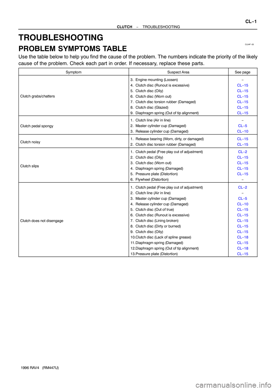
CL04F−03
− CLUTCHTROUBLESHOOTING
CL−1
1996 RAV4 (RM447U)
TROUBLESHOOTING
PROBLEM SYMPTOMS TABLE
Use the table below to help you find the cause of the problem. The numbers indicate the priority of the likely
cause of the problem. Check each part in order. If necessary, replace these parts.
SymptomSuspect AreaSee page
Clutch grabs/chatters
3. Engine mounting (Loosen)
4. Clutch disc (Runout is excessive)
5. Clutch disc (Oily)
6. Clutch disc (Worn out)
7. Clutch disc torsion rubber (Damaged)
8. Clutch disc (Glazed)
9. Diaphragm spring (Out of tip alignment)−
CL−15
CL−15
CL−15
CL−15
CL−15
CL−15
Clutch pedal spongy
1. Clutch line (Air in line)
2. Master cylinder cup (Damaged)
3. Release cylinder cup (Damaged)−
CL−5
CL−10
Clutch noisy1. Release bearing (Worn, dirty, or damaged)
2. Clutch disc torsion rubber (Damaged)CL−15
CL−15
Clutch slips
1. Clutch pedal (Free play out of adjustment)
2. Clutch disc (Oily)
3. Clutch disc (Worn out)
4. Diaphragm spring (Damaged)
5. Pressure plate (Distortion)
6. Flywheel (Distortion)CL−2
CL−15
CL−15
CL−15
CL−15
−
Clutch does not disengage
1. Clutch pedal (Free play out of adjustment)
2. Clutch line (Air in line)
3. Master cylinder cup (Damaged)
4. Release cylinder cup (Damaged)
5. Clutch disc (Out of true)
6. Clutch disc (Runout is excessive)
7. Clutch disc (Lining broken)
8. Clutch disc (Dirty or burned)
9. Clutch disc (Oily)
10.Clutch disc (Lack of spline grease)
11. Diaphragm spring (Damaged)
12.Diaphragm spring (Out of tip alignment)
13.Pressure plate (Distortion)CL−2
−
CL−5
CL−10
CL−15
CL−15
CL−15
CL−15
CL−15
CL−18
CL−15
CL−18
CL−15
Page 295 of 1354

CL04U−02
Q06037
Flywheel
Side
SST
Q06038
Matchmarks8 2, 5
6
SST
3
7 1, 4
Q06039SST
Q06245
CL−18
− CLUTCHCLUTCH UNIT
1996 RAV4 (RM447U)
INSTALLATION
1. INSTALL CLUTCH DISC AND CLUTCH COVER ON
FLYWHEEL
(a) Insert SST in the clutch disc, and then set them and the
clutch cover in position.
SST 09301−00220
(b) Align the matchmarks on the clutch cover and flywheel.
(c) Temporarily tighten the topmost bolt from the 3 near the
knock pins.
HINT:
Temporarily tighten the No.3 bolt.
(d) Torque the bolts on the clutch cover in the order shown.
Torque: 19 N·m (195 kgf·cm, 14 ft·lbf)
2. CHECK DIAPHRAGM SPRING TIP ALIGNMENT
Using a dial indicator with roller instrument, check the dia-
phragm spring tip alignment.
Maximum non−alignment: 0.5 mm (0.020 in.)
If alignment is not as specified, using SST, adjust the dia-
phragm spring tip alignment.
SST 09333−00013
3. APPLY MOLYBDENUM DISULPHIDE LITHIUM BASE
GREASE (NLGI NO.2)
(a) Apply release hub grease to the following parts.
�Release fork and hub contact point
�Release fork and push rod contact point
�Release fork pivot point
(b) Apply clutch spline grease.
�Clutch disc spline
HINT:
Recommended grease part number 08887−01706 (100g).
4. INSTALL RELEASE BEARING AND FORK TO TRANS-
AXLE
Install the bearing to the release fork, and then install them to
the transaxle.
5. INSTALL TRANSAXLE TO ENGINE
(2WD: See page MX−2)
(4WD: See page MX−8)
Page 745 of 1354
S01374
Cover
Connector
− ENGINE MECHANICALENGINE UNIT
EM−79
1996 RAV4 (RM447U)
25. INSTALL GENERATOR (See page CH−19)
26. INSTALL CHARCOAL CANISTER
27. CONNECT ENGINE WIRE TO RELAY BOX NO. 2
(a) Connect the engine wire to the relay block No.2 with the
2 nuts.
(b) Connect the connector.
(c) Install the upper cover.
(d) Connect the relay block No. 2 to the body with the 2 bolts.
28. INSTALL ACCELERATOR CABLE TO THROTTLE
BODY, CABLE BRACKET AND CLAMPS
29. INSTALL AIR CLEANER CASE AND CAP
30. INSTALL BATTERY
31. FILL WITH TRANSAXLE OIL
32. FILL WITH ENGINE OIL
33. FILL WITH ENGINE COOLANT
34. START ENGINE AND CHECK FOR LEAKS
35. PERFORM ENGINE ADJUSTMENT
36. CHECK FRONT WHEEL ALIGNMENT
37. INSTALL ENGINE UNDER COVERS
38. INSTALL ENGINE HOOD
39. ROAD TEST VEHICLE
Check for abnormal noises, shock slippage, correct shift points
and smooth operation.
40. RECHECK ENGINE COOLANT AND OIL LEVELS
Page 1002 of 1354
MX05P−05
− MANUAL TRANSAXLEMANUAL TRANSAXLE UNIT (2WD)
MX−7
1996 RAV4 (RM447U)
INSTALLATION
Installation is in the reverse order of removal.
(See page MX−3)
NOTICE:
When working with FIPG material, you must observe the following items.
�Using a razor blade and gasket scraper, remove all the old FIPG material from the gasket surfaces.
�Thoroughly clean all components to remove all the loose material.
�Clean both sealing surfaces with a non−residue solvent.
�Apply FIPG in an approx. 1 mm (0.04 in.) wide bead along the sealing surface.
�Parts must be assembled within 10 minutes of application. Otherwise, the FIPG material must be re-
moved and reapplied.
HINT:
After installation, check and inspect items as follows.
�Front wheel alignment (See page SA−4).
�Do the road test.
Page 1115 of 1354

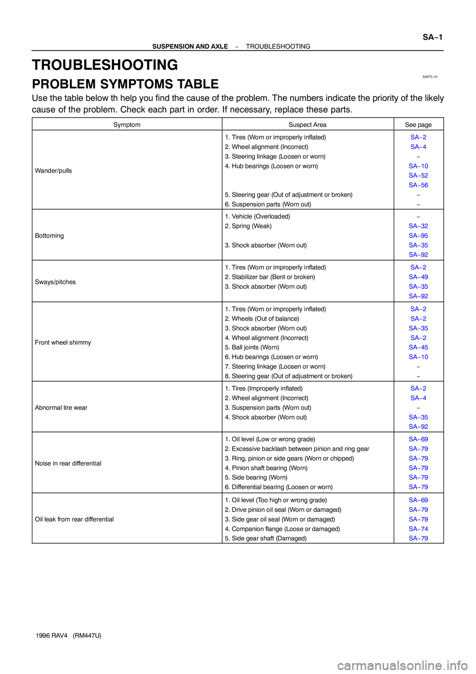
SA0T5−01
− SUSPENSION AND AXLETROUBLESHOOTING
SA−1
1996 RAV4 (RM447U)
TROUBLESHOOTING
PROBLEM SYMPTOMS TABLE
Use the table below th help you find the cause of the problem. The numbers indicate the priority of the likely
cause of the problem. Check each part in order. If necessary, replace these parts.
SymptomSuspect AreaSee page
Wander/pulls
1. Tires (Worn or improperly inflated)
2. Wheel alignment (Incorrect)
3. Steering linkage (Loosen or worn)
4. Hub bearings (Loosen or worn)
5. Steering gear (Out of adjustment or broken)
6. Suspension parts (Worn out)SA−2
SA−4
−
SA−10
SA−52
SA−56
−
−
Bottoming
1. Vehicle (Overloaded)
2. Spring (Weak)
3. Shock absorber (Worn out)−
SA−32
SA−95
SA−35
SA−92
Sways/pitches
1. Tires (Worn or improperly inflated)
2. Stabilizer bar (Bent or broken)
3. Shock absorber (Worn out)SA−2
SA−49
SA−35
SA−92
Front wheel shimmy
1. Tires (Worn or improperly inflated)
2. Wheels (Out of balance)
3. Shock absorber (Worn out)
4. Wheel alignment (Incorrect)
5. Ball joints (Worn)
6. Hub bearings (Loosen or worn)
7. Steering linkage (Loosen or worn)
8. Steering gear (Out of adjustment or broken)SA−2
SA−2
SA−35
SA−2
SA−45
SA−10
−
−
Abnormal tire wear
1. Tires (Improperly inflated)
2. Wheel alignment (Incorrect)
3. Suspension parts (Worn out)
4. Shock absorber (Worn out)SA−2
SA−4
−
SA−35
SA−92
Noise in rear differential
1. Oil level (Low or wrong grade)
2. Excessive backlash between pinion and ring gear
3. Ring, pinion or side gears (Worn or chipped)
4. Pinion shaft bearing (Worn)
5. Side bearing (Worn)
6. Differential bearing (Loosen or worn)SA−69
SA−79
SA−79
SA−79
SA−79
SA−79
Oil leak from rear differential
1. Oil level (Too high or wrong grade)
2. Drive pinion oil seal (Worn or damaged)
3. Side gear oil seal (Worn or damaged)
4. Companion flange (Loose or damaged)
5. Side gear shaft (Damaged)SA−69
SA−79
SA−79
SA−74
SA−79