Page 304 of 1354
CO0BJ−01
S01641
Thermostat
� Gasket
Water InletOil Filter
N·m (kgf·cm, ft·lbf): Specified torque
� Non−reusable part
8.8 (90, 78 in.·lbf)
− COOLINGTHERMOSTAT
CO−9
1996 RAV4 (RM447U)
THERMOSTAT
COMPONENTS
Page 305 of 1354
CO0BK−01
S01348
CO−10
− COOLINGTHERMOSTAT
1996 RAV4 (RM447U)
REMOVAL
HINT:
Removal of the thermostat would have an adverse effect, caus-
ing a lowering of cooling efficiency. Do not remove the thermo-
stat, even if the engine tends to overheat.
1. DRAIN ENGINE COOLANT
2. REMOVE OIL FILTER (See page LU−2)
3. REMOVE WATER INLET AND THERMOSTAT
(a) Remove the 2 nuts, and disconnect the water inlet from
the water pump cover.
(b) Remove the thermostat.
(c) Remove the gasket from the thermostat.
Page 307 of 1354
CO0BM−02
P13611
Protrusion
Jiggle
Valve5° 5° CO−12
− COOLINGTHERMOSTAT
1996 RAV4 (RM447U)
INSTALLATION
1. PLACE THERMOSTAT IN WATER PUMP
(a) Install a new gasket to the thermostat.
(b) Align the jiggle valve of the thermostat with the protrusion
of the water inlet, and insert the thermostat in the water
inlet.
HINT:
The jiggle valve may be set within 5° of either side of the pre-
scribed position.
2. INSTALL WATER INLET AND THERMOSTAT
Install the water inlet and thermostat with the 2 nuts.
Torque: 8.8 N·m (90 kgf·cm, 78 in.·lbf)
3. INSTALL OIL FILTER (See page LU−2)
4. FILL WITH ENGINE COOLANT
5. START ENGINE AND CHECK FOR LEAKS
6. CHECK ENGINE OIL LEVEL
Page 329 of 1354
P00495
Outside
Inside
− DIAGNOSTICSENGINE
DI−9
1996 RAV4 (RM447U)
4 Check air filter.
PREPARATION:
Remove air filter.
CHECK:
Visually check that the air cleaner element is not excessively
dirty or oily.
HINT:
If necessary, clean element with compressed air.
First blow from inside thoroughly,then blow from outside of ele-
ment.
NG Repair or replace.
OK
5 Check idle speed.
PREPARATION:
(a) Warm up engine to normal operating temperature.
(b) Switch off all accessories.
(c) Switch off air conditioning.
(d) Shift transmission into ”N” position.
(e) Connect the OBDII scan tool or TOYOTA hand−held tes-
ter to DLC3 on the vehicle.
CHECK:
Use CURRENT DATA to check the engine idle speed.
OK:
Idling speed: 650 − 750 rpm
NG Proceed to matrix chart of problem symptoms
on page DI−20.
OK
Page 728 of 1354

S01560
(1)
(2)
(3)
P15451
ConnectNew
New
Gasket
O−Ring
S01594
S01368
EM−62
− ENGINE MECHANICALCYLINDER HEAD
1996 RAV4 (RM447U)
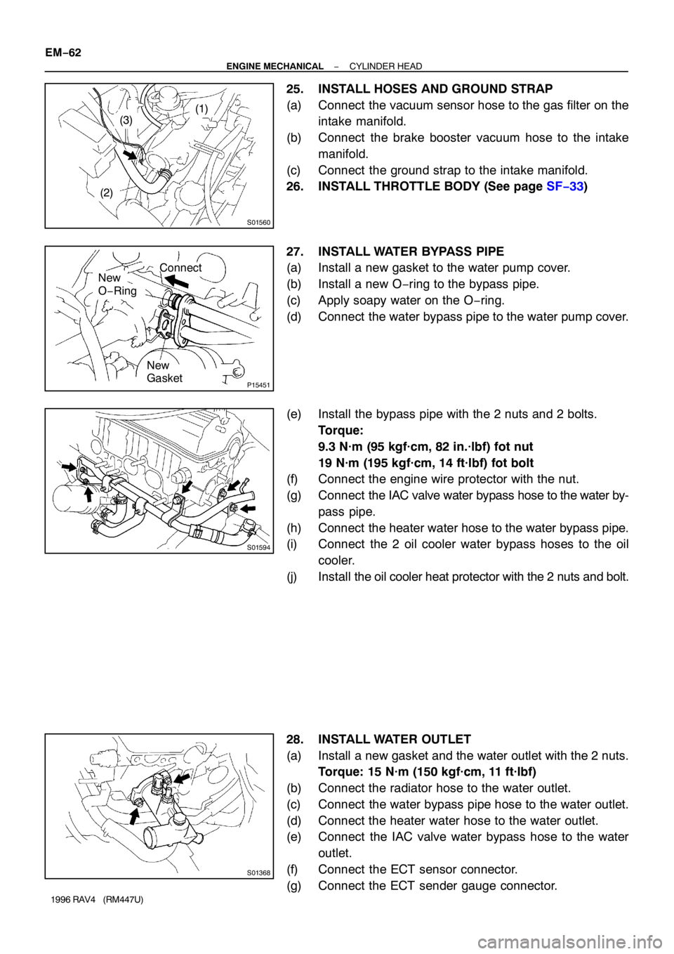
25. INSTALL HOSES AND GROUND STRAP
(a) Connect the vacuum sensor hose to the gas filter on the
intake manifold.
(b) Connect the brake booster vacuum hose to the intake
manifold.
(c) Connect the ground strap to the intake manifold.
26. INSTALL THROTTLE BODY (See page SF−33)
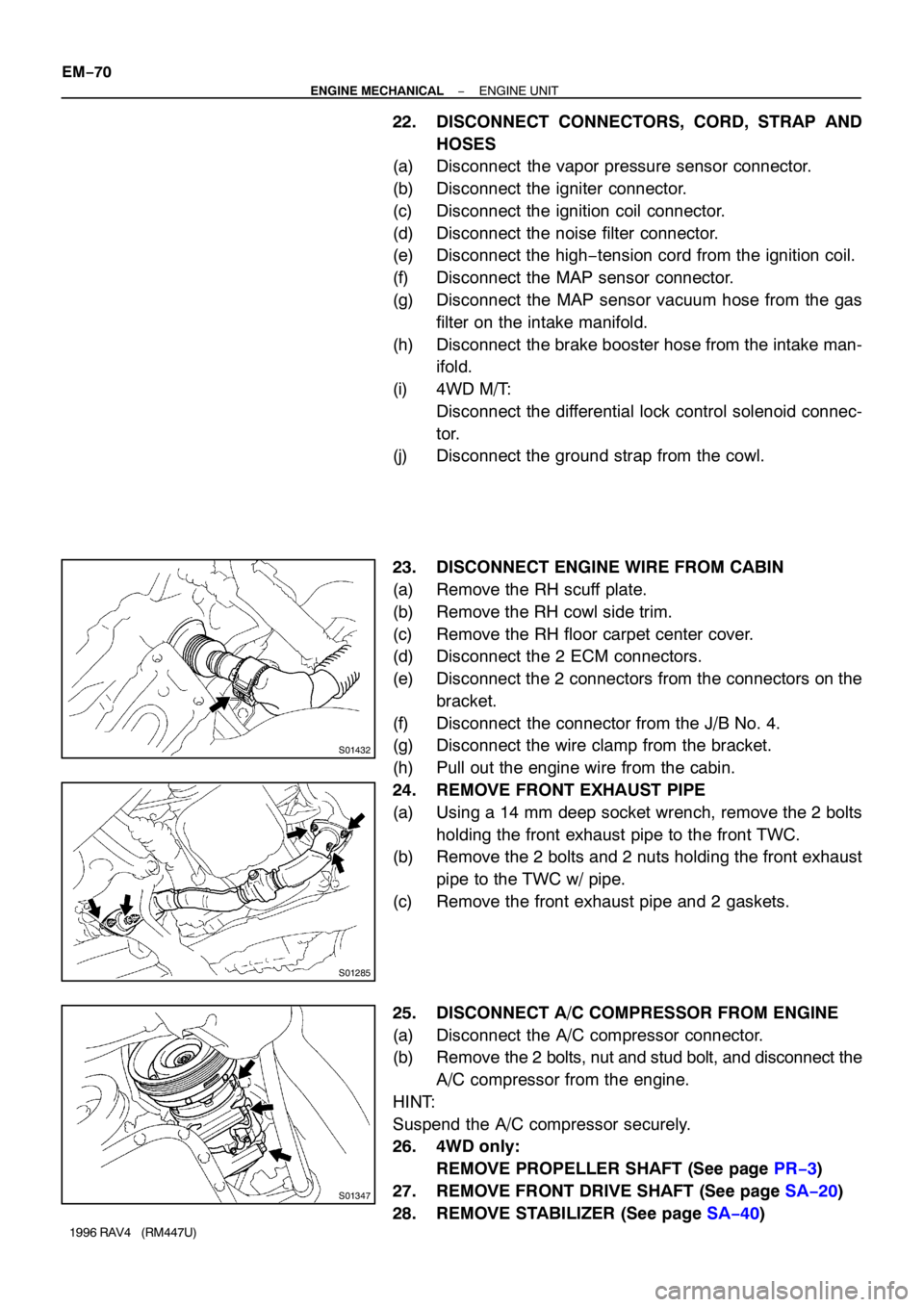
27. INSTALL WATER BYPASS PIPE
(a) Install a new gasket to the water pump cover.
(b) Install a new O−ring to the bypass pipe.
(c) Apply soapy water on the O−ring.
(d) Connect the water bypass pipe to the water pump cover.
(e) Install the bypass pipe with the 2 nuts and 2 bolts.
Torque:
9.3 N·m (95 kgf·cm, 82 in.·lbf) fot nut
19 N·m (195 kgf·cm, 14 ft·lbf) fot bolt
(f) Connect the engine wire protector with the nut.
(g) Connect the IAC valve water bypass hose to the water by-
pass pipe.
(h) Connect the heater water hose to the water bypass pipe.
(i) Connect the 2 oil cooler water bypass hoses to the oil
cooler.
(j) Install the oil cooler heat protector with the 2 nuts and bolt.
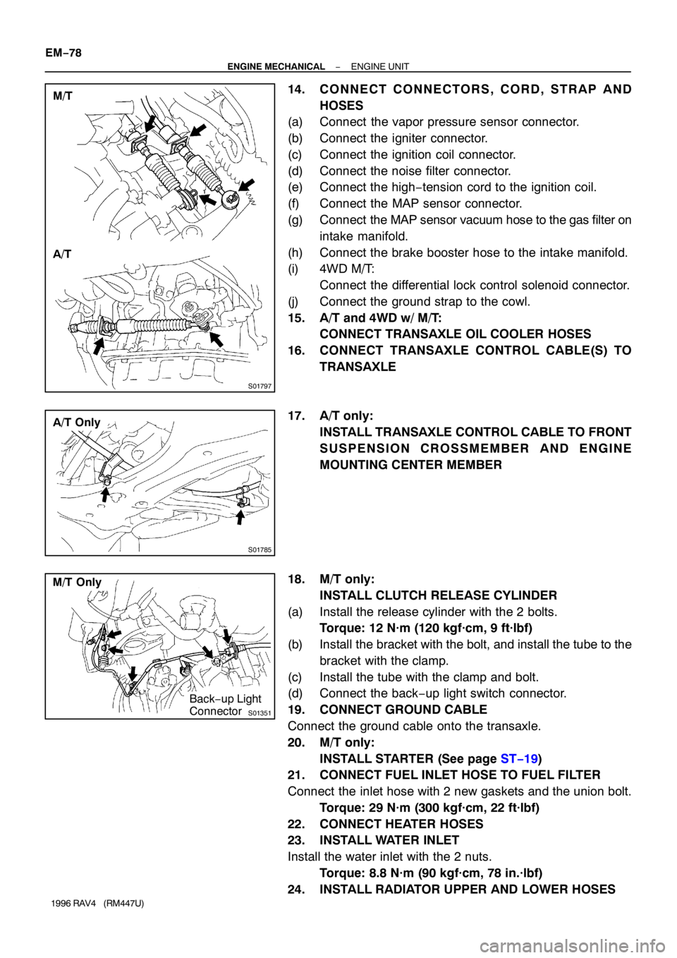
28. INSTALL WATER OUTLET
(a) Install a new gasket and the water outlet with the 2 nuts.
Torque: 15 N·m (150 kgf·cm, 11 ft·lbf)
(b) Connect the radiator hose to the water outlet.
(c) Connect the water bypass pipe hose to the water outlet.
(d) Connect the heater water hose to the water outlet.
(e) Connect the IAC valve water bypass hose to the water
outlet.
(f) Connect the ECT sensor connector.
(g) Connect the ECT sender gauge connector.
Page 736 of 1354

S01432
S01285
S01347
EM−70
− ENGINE MECHANICALENGINE UNIT
1996 RAV4 (RM447U)
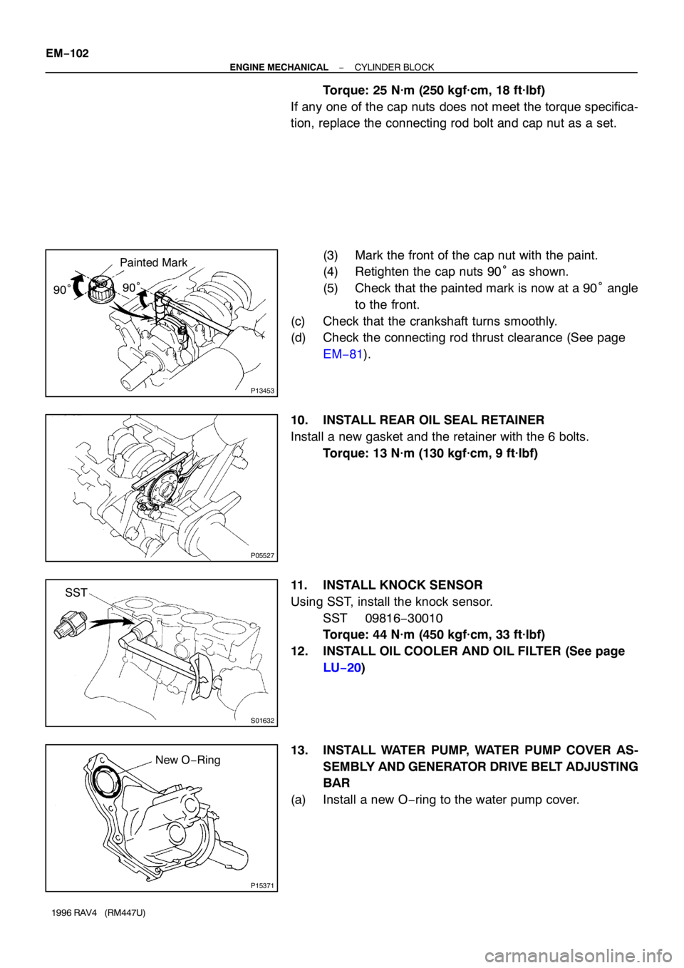
22. DISCONNECT CONNECTORS, CORD, STRAP AND
HOSES
(a) Disconnect the vapor pressure sensor connector.
(b) Disconnect the igniter connector.
(c) Disconnect the ignition coil connector.
(d) Disconnect the noise filter connector.
(e) Disconnect the high−tension cord from the ignition coil.
(f) Disconnect the MAP sensor connector.
(g) Disconnect the MAP sensor vacuum hose from the gas
filter on the intake manifold.
(h) Disconnect the brake booster hose from the intake man-
ifold.
(i) 4WD M/T:
Disconnect the differential lock control solenoid connec-
tor.
(j) Disconnect the ground strap from the cowl.
23. DISCONNECT ENGINE WIRE FROM CABIN
(a) Remove the RH scuff plate.
(b) Remove the RH cowl side trim.
(c) Remove the RH floor carpet center cover.
(d) Disconnect the 2 ECM connectors.
(e) Disconnect the 2 connectors from the connectors on the
bracket.
(f) Disconnect the connector from the J/B No. 4.
(g) Disconnect the wire clamp from the bracket.
(h) Pull out the engine wire from the cabin.
24. REMOVE FRONT EXHAUST PIPE
(a) Using a 14 mm deep socket wrench, remove the 2 bolts
holding the front exhaust pipe to the front TWC.
(b) Remove the 2 bolts and 2 nuts holding the front exhaust
pipe to the TWC w/ pipe.
(c) Remove the front exhaust pipe and 2 gaskets.
25. DISCONNECT A/C COMPRESSOR FROM ENGINE
(a) Disconnect the A/C compressor connector.
(b) Remove the 2 bolts, nut and stud bolt, and disconnect the
A/C compressor from the engine.
HINT:
Suspend the A/C compressor securely.
26. 4WD only:
REMOVE PROPELLER SHAFT (See page PR−3)
27. REMOVE FRONT DRIVE SHAFT (See page SA−20)
28. REMOVE STABILIZER (See page SA−40)
Page 744 of 1354

S01797
M/T
A/T
S01785
A/T Only
S01351
M/T Only
Back−up Light
Connector EM−78
− ENGINE MECHANICALENGINE UNIT
1996 RAV4 (RM447U)
14. CONNECT CONNECTORS, CORD, STRAP AND
HOSES
(a) Connect the vapor pressure sensor connector.
(b) Connect the igniter connector.
(c) Connect the ignition coil connector.
(d) Connect the noise filter connector.
(e) Connect the high−tension cord to the ignition coil.
(f) Connect the MAP sensor connector.
(g) Connect the MAP sensor vacuum hose to the gas filter on
intake manifold.
(h) Connect the brake booster hose to the intake manifold.
(i) 4WD M/T:
Connect the differential lock control solenoid connector.
(j) Connect the ground strap to the cowl.
15. A/T and 4WD w/ M/T:
CONNECT TRANSAXLE OIL COOLER HOSES
16. CONNECT TRANSAXLE CONTROL CABLE(S) TO
TRANSAXLE
17. A/T only:
INSTALL TRANSAXLE CONTROL CABLE TO FRONT
SUSPENSION CROSSMEMBER AND ENGINE
MOUNTING CENTER MEMBER
18. M/T only:
INSTALL CLUTCH RELEASE CYLINDER
(a) Install the release cylinder with the 2 bolts.
Torque: 12 N·m (120 kgf·cm, 9 ft·lbf)
(b) Install the bracket with the bolt, and install the tube to the
bracket with the clamp.
(c) Install the tube with the clamp and bolt.
(d) Connect the back−up light switch connector.
19. CONNECT GROUND CABLE
Connect the ground cable onto the transaxle.
20. M/T only:
INSTALL STARTER (See page ST−19)
21. CONNECT FUEL INLET HOSE TO FUEL FILTER
Connect the inlet hose with 2 new gaskets and the union bolt.
Torque: 29 N·m (300 kgf·cm, 22 ft·lbf)
22. CONNECT HEATER HOSES
23. INSTALL WATER INLET
Install the water inlet with the 2 nuts.
Torque: 8.8 N·m (90 kgf·cm, 78 in.·lbf)
24. INSTALL RADIATOR UPPER AND LOWER HOSES
Page 768 of 1354

P13453
Painted Mark
90°90°
P05527
S01632
SST
P15371
New O−Ring EM−102
− ENGINE MECHANICALCYLINDER BLOCK
1996 RAV4 (RM447U)
Torque: 25 N·m (250 kgf·cm, 18 ft·lbf)
If any one of the cap nuts does not meet the torque specifica-
tion, replace the connecting rod bolt and cap nut as a set.
(3) Mark the front of the cap nut with the paint.
(4) Retighten the cap nuts 90° as shown.
(5) Check that the painted mark is now at a 90° angle
to the front.
(c) Check that the crankshaft turns smoothly.
(d) Check the connecting rod thrust clearance (See page
EM−81).
10. INSTALL REAR OIL SEAL RETAINER
Install a new gasket and the retainer with the 6 bolts.
Torque: 13 N·m (130 kgf·cm, 9 ft·lbf)
11. INSTALL KNOCK SENSOR
Using SST, install the knock sensor.
SST 09816−30010
Torque: 44 N·m (450 kgf·cm, 33 ft·lbf)
12. INSTALL OIL COOLER AND OIL FILTER (See page
LU−20)
13. INSTALL WATER PUMP, WATER PUMP COVER AS-
SEMBLY AND GENERATOR DRIVE BELT ADJUSTING
BAR
(a) Install a new O−ring to the water pump cover.