Page 23 of 1354
AX04L−01
D00690
Planetary Gear Unit
O/D Direct
Clutch (C
0)O/D Brake (B0)1st & Reverse
Brake (B
3)
One−Way Clutch
No.2 (F
2)2nd Brake (B
2)
Forward
Clutch (C
1)2nd Coast
Brake (B
1)
Direct Clutch (C
2)
Input Shaft Front Planetary
Gear
One−Way Clutch
No.1 (F
1) Rear Planetary
Gear
Intermediate
Shaft Counter
Drive Gear
O/D Planetary
Gear O/D One−Way
Clutch (F
0)
Shift Lever
PositionGear Position
C
0C1C2B0B1B2B3F0F1F2
P Parking
Reverse
Neutral
1st
2nd
3rd
O/D R
N
D
2
L1st
2nd
*3rd
1st
*2nd�
�
�
�
�
�
�
�
�
�
��
�
�
�
�
�
�
�
��
�
�
��
�
��
�
�
�
�
��
��
�
�
�
�
�
�
��
�
��
�
�
*Down−shift only − no up−shift
� : Operating AX−2
− AUTOMATIC TRANSAXLE (A540H)AUTOMATIC TRANSAXLE SYSTEM
1996 RAV4 (RM447U)
OPERATION
Page 161 of 1354

TROUBLESHOOTING
PROBLEM SYMPTOMS TABLE
Use the table below to help you find the cause of the problem. The numbers indicate the priority")
BR02G−04
BR−2
− BRAKETROUBLESHOOTING
1996 RAV4 (RM447U)
TROUBLESHOOTING
PROBLEM SYMPTOMS TABLE
Use the table below to help you find the cause of the problem. The numbers indicate the priority of the likely
cause of the problem. Check each part in order. If necessary, replace these parts.
SymptomSuspect AreaSee page
Lower pedal or spongy pedal
1. Brake system (Fluid leaks)
2. Brake system (Air in)
3. Piston seals (Worn or damaged)
4. Rear Brake shoe clearance (Out of adjustment)
5. Master cylinder (Faulty)
6. Booster push rod (Out of adjustment)DI−282
−
BR−23
BR−33
BR−9
BR−19
Brake drag
1. Brake pedal freeplay (Minimal)
2. Parking brake lever travel (Out of adjustment)
3. Parking brake wire (Sticking)
4. Rear brake shoe clearance (Out of adjustment)
5. Pad or lining (Cracked or distorted)
6. Piston (Stuck)
7. Piston (Frozen)
8. Anchor or return spring (Faulty)
9. Booster push rod (Out of adjustment)
10. Booster system (Vacuum leaks)
11. Master cylinder (Faulty)BR−6
BR−8
−
BR−33
BR−20
BR−29
BR−23
BR−23
BR−29
BR−29
BR−19
BR−16
BR−9
Brake pull
1. Piston (Stuck)
2. Pad or lining (Oily)
3. Piston (Frozen)
4. Disc (Scored)
5. Pad or lining (Cracked or distorted)BR−23
BR−20
BR−29
BR−23
BR−29
BR−20
BR−20
BR−29
Page 166 of 1354
R00934
Pedal Reverse
Distance
− BRAKEBRAKE PEDAL
BR−7
1996 RAV4 (RM447U)
HINT:
The freeplay to the 1st point of resistance is due to the play be-
tween the clevis and pin. It is 1 − 3 mm (0.04 − 0.12 in.) on the
pedal.
If incorrect, check the stop light switch clearance. If the clear-
ance is OK, then troubleshoot the brake system.
4. CHECK PEDAL RESERVE DISTANCE
(a) Release the parking brake.
(b) With the engine running, depress the pedal and measure
the pedal reserve distance, as shown.
Pedal reserve distance from asphalt sheet at 490 N
(50 kgf, 110.2 lbf): More than 75 mm (2.95 in.)
If the reserve distance is incorrect, troubleshoot the brake sys-
tem.
Page 167 of 1354
R10698
BR02J−10
R10730
Lock Nut
Adjusting
Nut BR−8
− BRAKEPARKING BRAKE LEVER
1996 RAV4 (RM447U)
PARKING BRAKE LEVER
ON−VEHICLE INSPECTION
1. CHECK PARKING BRAKE LEVER TRAVEL
Pull the parking brake lever all the way up, and count the num-
ber of clicks.
Parking brake lever travel at 196 N (20 kgf, 44 lbf):
5 − 8 clicks
If incorrect, adjust the parking brake.
2. IF NECESSARY, ADJUST PARKING BRAKE
HINT:
Before adjusting the parking brake, make sure that the rear
brake shoe clearance has been adjusted. For shoe clearance
adjustment, see page BR−33.
(a) Remove the rear console box.
(b) Loosen the lock nut and turn the adjusting nut until the le-
ver travel is correct.
(c) Tighten the lock nut.
Torque: 5.4 N·m (55 kgf·cm, 48 in.·lbf)
(d) Install the rear console box.
Page 188 of 1354
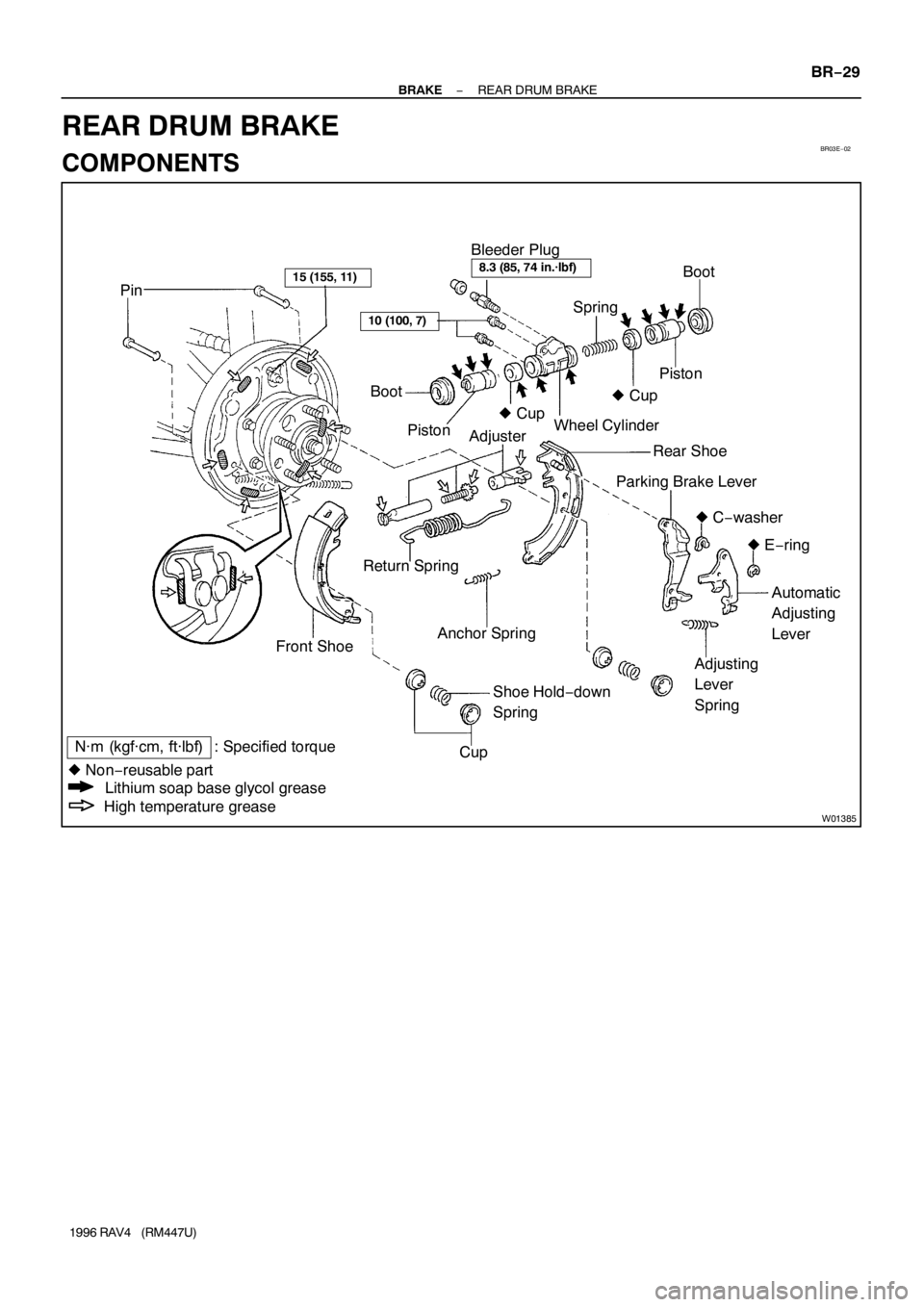
BR03E−02
W01385
PinBoot
� Cup Bleeder Plug
Piston Spring
AdjusterWheel Cylinder
Rear Shoe
Parking Brake Lever
� C−washer
� E−ring
Automatic
Adjusting
Lever
Adjusting
Lever
Spring Anchor Spring
Shoe Hold−down
Spring Return Spring
Front ShoeBoot
Piston� Cup
Cup15 (155, 11)8.3 (85, 74 in.·lbf)
10 (100, 7)
N·m (kgf·cm, ft·lbf) : Specified torque
� Non−reusable part
Lithium soap base glycol grease
High temperature grease
− BRAKEREAR DRUM BRAKE
BR−29
1996 RAV4 (RM447U)
REAR DRUM BRAKE
COMPONENTS
Page 190 of 1354
Z13290
SST
R10699
R10700
SST
BR0370
− BRAKEREAR DRUM BRAKE
BR−31
1996 RAV4 (RM447U)
5. REMOVE REAR SHOE
(a) Using SST, remove the shoe hold−down spring, cups and
pin.
SST 09718−00010
(b) Using a screwdriver, disconnect the parking brake cable
from the anchor plate.
(c) Using pliers, disconnect the parking brake cable from the
lever and remove the rear shoe together with the adjuster.
6. REMOVE ADJUSTER FROM REAR SHOE
(a) Remove the adjusting lever spring.
(b) Remove the adjuster together with the return spring.
7. DISCONNECT BRAKE LINE FROM WHEEL CYL-
INDER
Using SST, disconnect the brake line. Use a container to catch
the brake fluid.
SST 09023−00100
Torque: 15 N·m (155 kgf·cm, 11 ft·lbf)
8. REMOVE WHEEL CYLINDER
Remove the 2 bolts and the wheel cylinder.
Torque: 10 N·m (100 kgf·cm, 7 ft·lbf)
9. DISASSEMBLE WHEEL CYLINDER
Remove these parts from the wheel cylinder.
�2 boots
�2 pistons
�2 piston cups
�Spring
Page 192 of 1354

INSTALLATION
Installation is in the reverse order of removal (See page
BR−30).
1. AFTER INSTALLATION, FILL BRAKE RESERVOIR
WIT")
BR0M9−01
Z13455
− BRAKEREAR DRUM BRAKE
BR−33
1996 RAV4 (RM447U)
INSTALLATION
Installation is in the reverse order of removal (See page
BR−30).
1. AFTER INSTALLATION, FILL BRAKE RESERVOIR
WITH BRAKE FLUID, BLEED BRAKE SYSTEM (See
page BR−4) AND CHECK FOR LEAKS
NOTICE:
Apply lithium soap base glycol grease and high tempera-
ture grease to the parts indicated by the arrows (See page
BR−29).
2. CHECK OPERATION OF AUTOMATIC ADJUSTING
MECHANISM
(a) Move the parking brake lever of the rear shoe back and
forth. Check that the adjuster turns.
If the adjuster does not turn, check incorrect installation of the
rear brake.
(b) Adjust the adjuster length to the shortest possible
amount.
(c) Install the brake drum.
(d) Pull the parking brake lever all the way up until a clicking
sound can no longer be heard.
3. CHECK CLEARANCE BETWEEN BRAKE SHOES AND
DRUM
(a) Remove the brake drum.
(b) Measure the brake drum inside diameter and diameter of
the brake shoes. Check that the difference between the
diameters is the correct shoe clearance.
Shoe clearance: 0.6 mm (0.024 in.)
If incorrect, check the parking brake system.
Page 205 of 1354
BR03Z−02
R10729
R10704
BR−46
− BRAKEREAR SPEED SENSOR
1996 RAV4 (RM447U)
REMOVAL
1. DISCONNECT SPEED SENSOR CONNECTOR
(a) Remove the seat cushion and rear side trim.
(b) Disconnect the speed sensor connector, and pull out the
sensor wire harness with grommet.
(c) Disconnect the parking brake cable from the suspension
arm.
(d) Remove the 3 clamp bolts holding the sensor wire har-
ness to the body and suspension arm.
Torque:
To body: 5.0 N·m (55 kgf·cm, 49 in.·lbf)
To suspension arm: 13 N·m (130 kgf·cm, 9 ft·lbf)
2. 2WD:
REMOVE SPEED SENSOR WITH AXLE HUB
(See page SA−52)
3. 4WD:
REMOVE SPEED SENSOR
Remove the speed sensor from the axle carrier.
Torque: 8.0 N·m (80 kgf·cm, 69 in.·lbf)
O/D Brake (B0)1st & Reverse
Brake (B
3)
One−Way Clutch
No.2 (F
2)2nd Brake (B
2)
Forward
Clutch (C
1)2nd Coast
Brake (B
1)
Direct Clutch")

HINT:
The freeplay to the 1st point of resistance is due to the play be-
tween the clevis and pin. It is 1 − 3 mm (0.04")

PARKING BRAKE LEVER
ON−VEHICLE INSPECTION
1. CHECK PARKING BRAKE LEVER TRAVEL
Pull the parkin")

5. REMOVE REAR SHOE
(a) Using SST, remove the shoe hold−down spring, cups and
pin.
SST 09718−00010
(b) Usi")

REMOVAL
1. DISCONNECT SPEED SENSOR CONNECTOR
(a) Remove the seat cushion and rear side trim.
(b) Disconnect the speed s")