Page 15 of 1354
D02186
AX127−01
Q08747
Q08761
D02187
Q08763
− AUTOMATIC TRANSAXLE (A241E)AUTOMATIC TRANSAXLE UNIT
AX−15
1996 RAV4 (RM447U)
REMOVAL
1. DISCONNECT THROTTLE CABLE
2. REMOVE ENGINE COOLANT RESERVOIR TANK
3. REMOVE AIR CLEANER ASSEMBLY
(a) Disconnect the connector and ABS relay.
(b) Remove the 3 bolts and air cleaner assembly.
4. REMOVE GROUND CABLE
Remove the bolt from the transaxle.
Torque: 19 N·m (194 kgf·cm, 14 ft·lbf)
5. REMOVE SET NUT OF ENGINE WIRE CLAMP
6. REMOVE STARTER
(a) Disconnect the connector and nut from the starter.
(b) Remove the 2 bolts and disconnect the engine wire.
Torque: 39 N·m (400 kgf·cm, 29 ft·lbf)
(c) Remove the starter.
7. REMOVE 3 UPPER SIDE TRANSAXLE MOUNTING
BOLTS
Torque: 64 N·m (650 kgf·cm, 47 ft·lbf)
8. INSTALL ENGINE SUPPORT FIXTURE
Page 40 of 1354

Q06113
AX04U−02
Q05857
Z19463
Q05858
− AUTOMATIC TRANSAXLE (A540H)AUTOMATIC TRANSAXLE UNIT
AX−19
1996 RAV4 (RM447U)
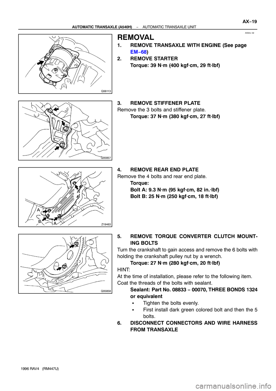
REMOVAL
1. REMOVE TRANSAXLE WITH ENGINE (See page
EM−68)
2. REMOVE STARTER
Torque: 39 N·m (400 kgf·cm, 29 ft·lbf)
3. REMOVE STIFFENER PLATE
Remove the 3 bolts and stiffener plate.
Torque: 37 N·m (380 kgf·cm, 27 ft·lbf)
4. REMOVE REAR END PLATE
Remove the 4 bolts and rear end plate.
Torque:
Bolt A: 9.3 N·m (95 kgf·cm, 82 in.·lbf)
Bolt B: 25 N·m (250 kgf·cm, 18 ft·lbf)
5. REMOVE TORQUE CONVERTER CLUTCH MOUNT-
ING BOLTS
Turn the crankshaft to gain access and remove the 6 bolts with
holding the crankshaft pulley nut by a wrench.
Torque: 27 N·m (280 kgf·cm, 20 ft·lbf)
HINT:
At the time of installation, please refer to the following item.
Coat the threads of the bolts with sealant.
Sealant: Part No. 08833 − 00070, THREE BONDS 1324
or equivalent
�Tighten the bolts evenly.
�First install dark green colored bolt and then the 5
bolts.
6. DISCONNECT CONNECTORS AND WIRE HARNESS
FROM TRANSAXLE
Page 293 of 1354
CL04S−02
Q06030
Matchmarks
Q06031
CL−16
− CLUTCHCLUTCH UNIT
1996 RAV4 (RM447U)
REMOVAL
1. REMOVE TRANSAXLE FROM ENGINE
(2WD: See page MX−2)
(4WD: See page MX−8)
2. REMOVE CLUTCH COVER AND DISC
(a) Place matchmarks on the flywheel and clutch cover.
(b) Loosen each set bolt one turn at a time until spring tension
is released.
(c) Remove the set bolts, and pull off the clutch cover with the
clutch disc.
NOTICE:
Do not drop the clutch disc.
3. REMOVE RELEASE BEARING AND FORK FROM
TRANSAXLE
(a) Remove the release bearing together with the fork and
then separate them.
(b) Remove the boot.
Page 300 of 1354
CO0BG−02
S01613
P15462
P15546
1
3
2
P15463
Disconnect
− COOLINGWATER PUMP
CO−5
1996 RAV4 (RM447U)
REMOVAL
1. REMOVE RH ENGINE UNDER COVER
2. DRAIN ENGINE COOLANT
3. REMOVE TIMING BELT (See page EM−15)
4. DISCONNECT LOWER RADIATOR HOSE FROM
WATER INLET
5. REMOVE TIMING BELT TENSION SPRING AND NO.2
IDLER PULLEY
6. REMOVE GENERATOR DRIVE BELT ADJUSTING
BAR
(a) Disconnect the crankshaft position sensor connector
clamp.
(b) Remove the bolt and adjusting bar.
7. REMOVE WATER PUMP AND WATER PUMP COVER
ASSEMBLY
(a) Remove the 2 nuts holding the water pump to the water
bypass pipe.
(b) Remove the 3 bolts in the sequence shown.
(c) Disconnect the water pump cover from the water bypass
pipe, and remove the water pump and water pump cover
assembly.
(d) Remove the gasket and 2 O−ring from the water pump
and water bypass pipe.
Page 305 of 1354
CO0BK−01
S01348
CO−10
− COOLINGTHERMOSTAT
1996 RAV4 (RM447U)
REMOVAL
HINT:
Removal of the thermostat would have an adverse effect, caus-
ing a lowering of cooling efficiency. Do not remove the thermo-
stat, even if the engine tends to overheat.
1. DRAIN ENGINE COOLANT
2. REMOVE OIL FILTER (See page LU−2)
3. REMOVE WATER INLET AND THERMOSTAT
(a) Remove the 2 nuts, and disconnect the water inlet from
the water pump cover.
(b) Remove the thermostat.
(c) Remove the gasket from the thermostat.
Page 311 of 1354

CO0BQ−03
S01355
S01278
w/ A/C
S01293
CO−16
− COOLINGRADIATOR
1996 RAV4 (RM447U)
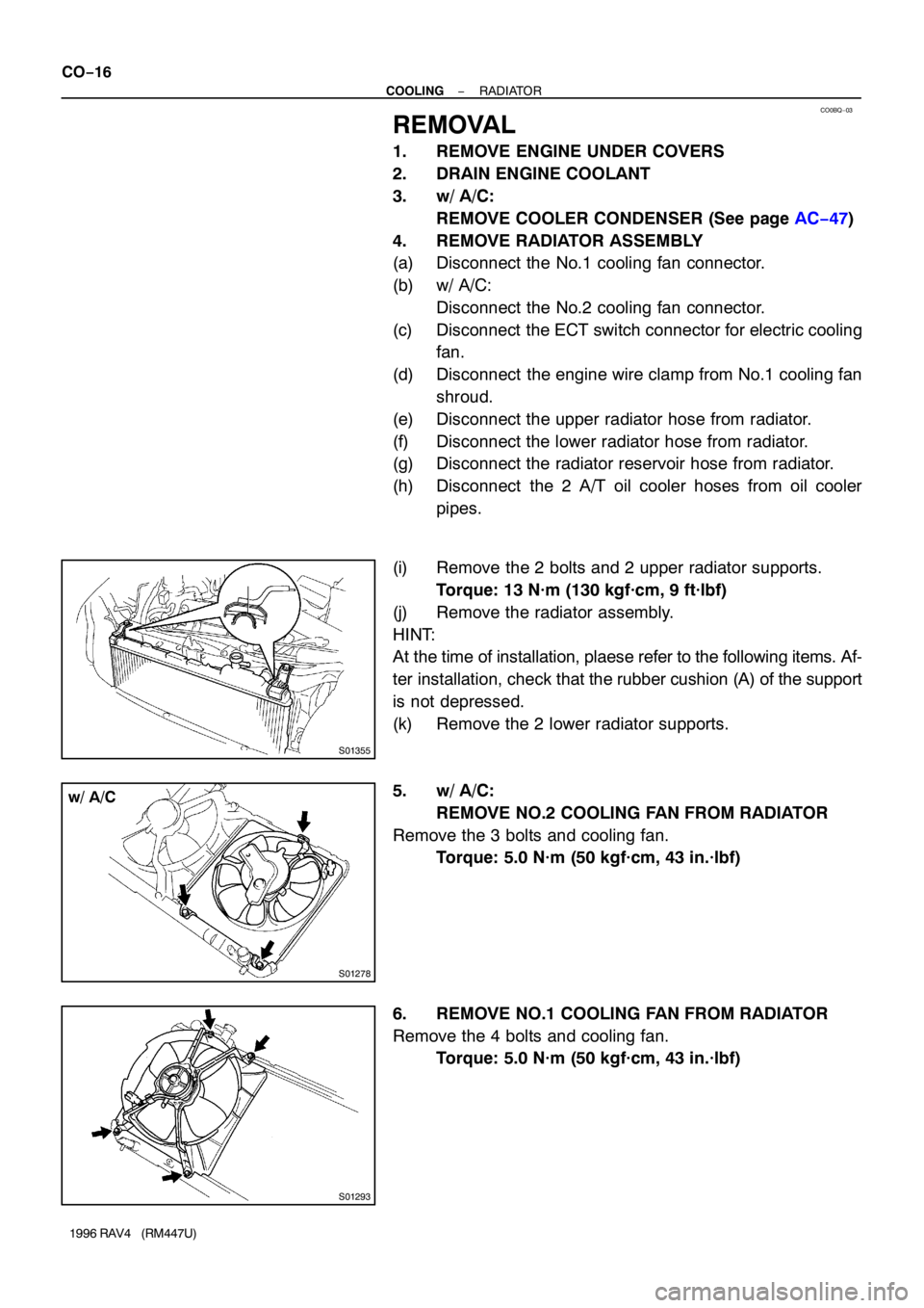
REMOVAL
1. REMOVE ENGINE UNDER COVERS
2. DRAIN ENGINE COOLANT
3. w/ A/C:
REMOVE COOLER CONDENSER (See page AC−47)
4. REMOVE RADIATOR ASSEMBLY
(a) Disconnect the No.1 cooling fan connector.
(b) w/ A/C:
Disconnect the No.2 cooling fan connector.
(c) Disconnect the ECT switch connector for electric cooling
fan.
(d) Disconnect the engine wire clamp from No.1 cooling fan
shroud.
(e) Disconnect the upper radiator hose from radiator.
(f) Disconnect the lower radiator hose from radiator.
(g) Disconnect the radiator reservoir hose from radiator.
(h) Disconnect the 2 A/T oil cooler hoses from oil cooler
pipes.
(i) Remove the 2 bolts and 2 upper radiator supports.
Torque: 13 N·m (130 kgf·cm, 9 ft·lbf)
(j) Remove the radiator assembly.
HINT:
At the time of installation, plaese refer to the following items. Af-
ter installation, check that the rubber cushion (A) of the support
is not depressed.
(k) Remove the 2 lower radiator supports.
5. w/ A/C:
REMOVE NO.2 COOLING FAN FROM RADIATOR
Remove the 3 bolts and cooling fan.
Torque: 5.0 N·m (50 kgf·cm, 43 in.·lbf)
6. REMOVE NO.1 COOLING FAN FROM RADIATOR
Remove the 4 bolts and cooling fan.
Torque: 5.0 N·m (50 kgf·cm, 43 in.·lbf)
Page 316 of 1354
CO18L−01
S01356
(A)
S01433
− COOLINGELECTRIC COOLING FAN
CO−21
1996 RAV4 (RM447U)
REMOVAL
1. REMOVE NO.1 COOLING FAN (See page CO−16)
2. REMOVE NO.2 COOLING FAN
(a) Remove the RH engine under cover.
(b) w/ A/C:
Remove the cooler condenser (See page AC−47).
(c) Remove the upper radiator supports.
Torque:13 N·m (130kgf·cm, 9 ft·lbf)
HINT:
At the time of installation, plaese refer to the following items. Af-
ter installation, check that the rubber cushion (A) of the support
is not depressed.
(d) Remove the No.2 cooling fan.
(1) Disconnect the cooling fan connector.
(2) Push the radiator toward the front bumper.
(3) Remove the 3 bolts.
(4) Push the No.2 cooling fan toward radiator and pull
it upward.
Page 681 of 1354

EM0EM−03
S01283
B
SST
A
S01358
Oil Pump
S01630
SST
SST
− ENGINE MECHANICALTIMING BELT
EM−15
1996 RAV4 (RM447U)
REMOVAL
1. DISCONNECT PS RESERVOIR AND REMOVE RES-
ERVOIR BRACKET
2. DISCONNECT WIRE HARNESS BRACKET FOR DLC1
3. REMOVE GENERATOR (See page CH−7)
4. REMOVE GENERATOR BRACKET
5. w/ ABS:
REMOVE NO. 3 ABS ACTUATOR BRACKET (See page
BR−40)
6. REMOVE RH FRONT WHEEL
7. REMOVE RH ENGINE UNDER COVER
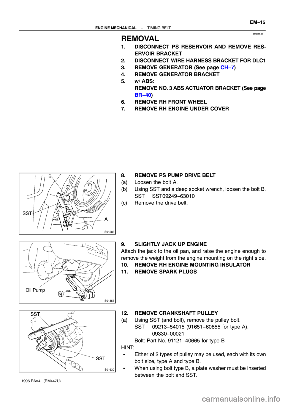
8. REMOVE PS PUMP DRIVE BELT
(a) Loosen the bolt A.
(b) Using SST and a deep socket wrench, loosen the bolt B.
SST SST09249−63010
(c) Remove the drive belt.
9. SLIGHTLY JACK UP ENGINE
Attach the jack to the oil pan, and raise the engine enough to
remove the weight from the engine mounting on the right side.
10. REMOVE RH ENGINE MOUNTING INSULATOR
11. REMOVE SPARK PLUGS
12. REMOVE CRANKSHAFT PULLEY
(a) Using SST (and bolt), remove the pulley bolt.
SST 09213−54015 (91651−60855 for type A),
09330−00021
Bolt: Part No. 91121−40665 for type B
HINT:
�Either of 2 types of pulley may be used, each with its own
bolt size, type A and type B.
�When using bolt type B, a plate washer must be inserted
between the bolt and SST.