Page 5 of 1354
VALVE BODY ASSEMBLY
AX−5
1996 RAV4 (RM447U)
VALVE BODY ASSEMBLY
ON−VEHICLE REPAIR
1. REMOVE DRAIN PLUG AND DRAIN ATF
2. REMO")
AX0T6−02
Q05259
Q05234
Q06417
Q06418
− AUTOMATIC TRANSAXLE (A241E)VALVE BODY ASSEMBLY
AX−5
1996 RAV4 (RM447U)
VALVE BODY ASSEMBLY
ON−VEHICLE REPAIR
1. REMOVE DRAIN PLUG AND DRAIN ATF
2. REMOVE OIL PAN AND GASKET
Remove the 18 bolts.
NOTICE:
Some fluid will remain in the oil pan. Remove all pan bolts,
and carefully remove the oil pan assembly. Discard the
gasket.
3. EXAMINE PARTICLES IN PAN
Remove the magnets and use them to collect any steel chips.
Look carefully at the chips and particles in the pan and the mag-
net to anticipate what type of wear you will find in the transaxle.
�Steel (magnetic): bearing, gear and plate wear
�Brass (non−magnetic): bearing wear
4. REMOVE OIL STRAINER AND APPLY PIPE BRACKET
NOTICE:
Be careful as some fluid will come out with the oil strainer.
(a) Remove the 3 bolts, oil strainer and gasket.
(b) Remove the 2 bolts and apply pipe bracket.
5. REMOVE OIL PIPE CLAMP AND OIL PIPES
(a) Remove the bolt and oil pipe clamp.
(b) Pry up the both pipe ends with a large screwdriver and re-
move the 5 pipes.
NOTICE:
Be careful not to bend or damage the pipe.
Page 8 of 1354
Q06417
Q05234
Q05259
AX−8
− AUTOMATIC TRANSAXLE (A241E)VALVE BODY ASSEMBLY
1996 RAV4 (RM447U)
15. INSTALL OIL STRAINER AND APPLY PIPE BRACKET
Install the oil strainer, gasket with the 3 bolts.
Torque: 10 N·m (102 kgf·cm, 7 ft·lbf)
HINT:
Replace used the gasket with a new one.
16. INSTALL 2 MAGNETS IN OIL PAN
17. INSTALL OIL PAN AND GASKET
(a) Install a new gasket to the oil pan.
(b) Install the oil pan with the 18 bolts.
Torque: 4.9 N·m (50 kgf·cm, 43 in.·lbf)
18. INSTALL DRAIN PLUG
Torque: 17 N·m (175 kgf·cm, 13 ft·lbf)
19. FILL ATF AND CHECK ATF (See page DI−127)
Page 29 of 1354
Q06064
AX129−01
AT0103
D00691
D00692
AX−8
− AUTOMATIC TRANSAXLE (A540H)VALVE BODY ASSEMBLY
1996 RAV4 (RM447U)
VALVE BODY ASSEMBLY
ON−VEHICLE REPAIR
1. REMOVE NO.2 ENGINE UNDER COVER
2. DRAIN ATF
Using a 10 mm hexagon wrench, remove the drain plug, and
drain the ATF into a suitable container.
3. REMOVE OIL PAN AND GASKET
(a) Remove the 17 bolts.
(b) Remove the oil pan by lifting transaxle case.
NOTICE:
Some fluid remain in the oil pan.
4. EXHAUST PARTICLES IN PAN
Remove the magnet and use it to collect any steel chips.
Lock carefully at the chips and particles in the oil pan and on the
magnet to anticipate when type of wear you will find in the trans-
axle.
�Steel (magnetic): bearing, gear and plate wear
�Brass (non−magnetic): bushing wear
5. REMOVE OIL PIPE BRACKET AND STRAINER
(a) Remove the 2 bolts and oil pipe bracket.
(b) Remove the 3 bolts and strainer.
(c) Remove the gasket from the strainer.
6. REMOVE MANUAL VALVE BODY
(a) Remove the 2 bolts and detent spring.
Page 33 of 1354
VALVE BODY ASSEMBLY
1996 RAV4 (RM447U)
(d) Place the detent springs on the manual valve body and
hand−tighten the 2 bo")
Z13390A B
Z13391
A
BA
B
Q06019
Q06064
AX−12
− AUTOMATIC TRANSAXLE (A540H)VALVE BODY ASSEMBLY
1996 RAV4 (RM447U)
(d) Place the detent springs on the manual valve body and
hand−tighten the 2 bolts first.
Then, tighten them with a torque wrench.
Torque: 11 N·m (110 kgf·cm, 8 ft·lbf)
HINT:
Each bolt length is indicated below.
Bolt length:
Bolt A: 14 mm (0.55 in.)
Bolt B: 37 mm (1.46 in.)
(e) Check that the manual valve lever is touching the center
of the detent spring tip roller.
18. INSTALL PIPE BRACKET AND OIL STRAINER
Torque: 11 N·m (110 kgf·cm, 8 ft·lbf)
HINT:
Each bolt length is indicated below.
Bolt length:
Bolt A: 22 mm (0.87 in.)
Bolt B: 53 mm (2.09 in.)
19. INSTALL MAGNETS IN PLACE
NOTICE:
Make sure that the magnets do not interfere with the oil
pipes.
20. INSTALL OIL PAN WITH NEW GASKET
(a) Install a new gasket and oil pan.
(b) Install and tighten 17 bolts.
Torque: 7.9 N·m (80 kgf·cm, 70 in.·lbf)
21. FILL ATF AND CHECK FLUID LEVEL
(a) Using a 10 mm hexagon wrench, install a new gasket and
the drain plug.
Torque: 49 N·m (500 kgf·cm, 36 ft·lbf)
(b) Fill the ATF and check the fluid level (See page DI−173).
22. INSTALL NO.2 ENGINE UNDER COVER
Page 765 of 1354

Front Mark
(Protrusion)
Z17148
Code Mark
No. 1
No. 2Code Mark
S01227
Upper Side Rail
Expander
No. 2
Compression
RingLower Side
Rail No. 1 Compression
Ring
Front M")
EM1BD−02
S01247
Front Mark
(Cavity)
Front Mark
(Protrusion)
Z17148
Code Mark
No. 1
No. 2Code Mark
S01227
Upper Side Rail
Expander
No. 2
Compression
RingLower Side
Rail No. 1 Compression
Ring
Front Mark
(Cavity)
P00797
− ENGINE MECHANICALCYLINDER BLOCK
EM−99
1996 RAV4 (RM447U)
REASSEMBLY
HINT:
�Thoroughly clean all parts to be assembled.
�Before installing the parts, apply new engine oil to all slid-
ing and rotating surfaces.
�Replace all gaskets, O−rings and oil seals with new parts.
1. ASSEMBLE PISTON AND CONNECTING ROD
(a) Install a small screwdriver, install a new snap ring on one
side of the piston pin hole.
(b) Gradually heat the piston to 80 − 90°C (176 − 194°F).
(c) Coat the piston pin with engine oil.
(d) Align the front marks of the piston and connecting rod,
and push in the piston pin with your thumb.
(e) Install a small screwdriver, install a new snap ring on the
other side of the piston pin hole.
2. INSTALL PISTON RINGS
(a) Install the oil ring expander and 2 side rails by hand.
(b) Using a piston ring expander, install the 2 compression
rings with the code mark facing upward.
Code mark:
No. 11N or T
No. 22N or 2T
(c) Position the piston rings so that the ring ends are as
shown.
NOTICE:
Do not align the ring ends.
3. INSTALL BEARINGS
(a) Align the bearing claw with the groove of the connecting
rod or connecting cap.
(b) Install the bearings in the connecting rod and connecting
rod cap.
Page 983 of 1354
P04349
S02326
Engine
Hanger
No.1
S01635
SST
S01599
S01581
LU−8
− LUBRICATIONOIL PUMP
1996 RAV4 (RM447U)
7. REMOVE OIL PAN BAFFLE PLATE AND OIL STRAIN-
ER
Remove the 2 bolts, 2 nuts, oil strainer, baffle plate and gasket.
8. SUSPEND ENGINE WITH ENGINE SLING DEVICE
Install a engine hanger No. 1 in the correct direction.
Part No. :
Engine hanger No. 1 12281−74060
Bolt 91611−B1020
Torque: 25 N·m (250 kgf·cm, 18 ft·lbf)
9. REMOVE TIMING BELT (See page EM−15)
10. REMOVE NO.2 IDLER PULLEY AND CRANKSHAFT
TIMING PULLEY (See page EM−81)
11. REMOVE OIL PUMP PULLEY
Using SST, remove the nut and pulley.
SST 09960−10010 (09962−01000, 09963−00600)
12. REMOVE CRANKSHAFT POSITION SENSOR
(a) Disconnect the connector from the generator drive belt
adjusting bar.
(b) Remove the bolt and crankshaft position sensor.
13. REMOVE OIL PUMP
(a) Remove the 12 bolts.
Page 990 of 1354

S01375
− LUBRICATIONOIL PUMP
LU−15
1996 RAV4 (RM447U)
7. INSTALL OIL PAN BAFFLE PLATE AND OIL STRAIN-
ER
Install a new gasket, the oil strainer")
P04349
LU0420
Seal Width
ABC
A
B
C
5mm (0.20 in.)
S01375
− LUBRICATIONOIL PUMP
LU−15
1996 RAV4 (RM447U)
7. INSTALL OIL PAN BAFFLE PLATE AND OIL STRAIN-
ER
Install a new gasket, the oil strainer and baffle plate with the 2
bolts and 2 nuts.
Torque: 5.4 N·m (55 kgf·cm, 48 in.·lbf)
8. INSTALL OIL PAN
(a) Remove any old packing (FIPG) material and be careful
not to drop any oil on the contact surfaces of the oil pan
and cylinder block.
�Using a razor blade and gasket scraper, remove all
the old packing (FIPG) material from the gasket sur-
faces and sealing groove.
�Thoroughly clean all components to remove all the
loose material.
�Using a non−residue solvent, clean both sealing
surfaces.
NOTICE:
Do not use a solvent which will affect the painted surfaces.
(b) Apply seal packing to the oil pan as shown in the illustra-
tion.
Seal packing:
Part No.08826−00080 or equivalent
�Install a nozzle that has been cut to a 3−5 mm (0.12
− 0.20 in.) opening.
�Parts must be assembled within 5 minutes of ap-
plication. Otherwise the material must be removed
and reapplied.
�Immediately remove nozzle from the tube and rein-
stall cap.
(c) Install the oil pan with 17 bolts and 2 nuts.
Torque: 5.4 N·m (55 kgf·cm, 48 in.·lbf)
(d) Install the dipstick.
Page 1182 of 1354
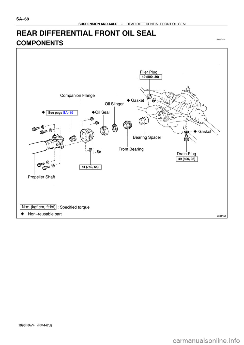
SA0UG−01
W04154
Filer Plug
Companion Flange
Oil Slinger
Oil Seal
Front BearingBearing Spacer
Drain PlugGasket
Propeller Shaft�
49 (500, 36)
49 (500, 36)
74 (750, 54)
� Gasket �
�
N·m (kgf·cm, ft·lbf)
: Specified torque
�Non−reusable part
See page SA−79
SA−68
− SUSPENSION AND AXLEREAR DIFFERENTIAL FRONT OIL SEAL
1996 RAV4 (RM447U)
REAR DIFFERENTIAL FRONT OIL SEAL
COMPONENTS
VALVE BODY ASSEMBLY
1996 RAV4 (RM447U)
15. INSTALL OIL STRAINER AND APPLY PIPE BRACKET
Install the oil strainer, gasket with the 3 bolts.
T")
VALVE BODY ASSEMBLY
1996 RAV4 (RM447U)
VALVE BODY ASSEMBLY
ON−VEHICLE REPAIR
1. REMOVE NO.2 ENGINE UNDER COVER
2. DRAIN")

7. REMOVE OIL PAN BAFFLE PLATE AND OIL STRAIN-
ER
Remove the 2 bolts, 2 nuts, oil strainer")