Page 335 of 1354

− DIAGNOSTICSENGINE
DI−15
1996 RAV4 (RM447U) DTC No.
(See Page)
Detection ItemTrouble AreaMILMemory
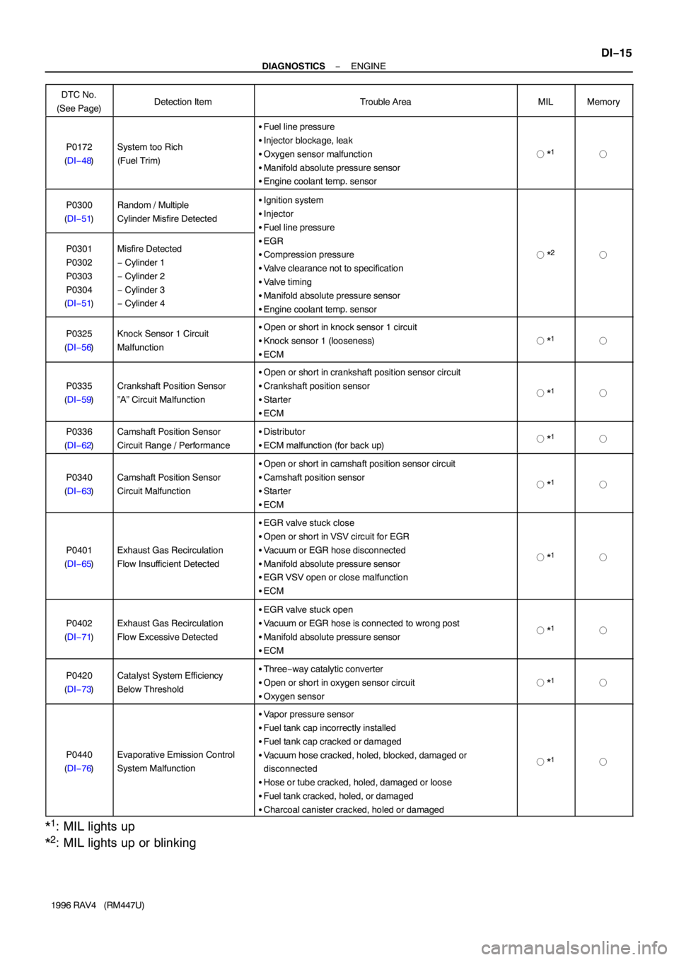
P0172
(DI−48)System too Rich
(Fuel Trim)
�Fuel line pressure
�Injector blockage, leak
�Oxygen sensor malfunction
�Manifold absolute pressure sensor
�Engine coolant temp. sensor
� *1�
P0300
(DI−51)Random / Multiple
Cylinder Misfire Detected�Ignition system
�Injector
�Fuel line pressure
�EGR
�Compression pressure
�Valve clearance not to specification
�Valve timing
�Manifold absolute pressure sensor
�Engine coolant temp. sensor
� *2�P0301
P0302
P0303
P0304
(DI−51)Misfire Detected
− Cylinder 1
− Cylinder 2
− Cylinder 3
− Cylinder 4
P0325
(DI−56)Knock Sensor 1 Circuit
Malfunction�Open or short in knock sensor 1 circuit
�Knock sensor 1 (looseness)
�ECM
� *1�
P0335
(DI−59)Crankshaft Position Sensor
”A” Circuit Malfunction
�Open or short in crankshaft position sensor circuit
�Crankshaft position sensor
�Starter
�ECM
� *1�
P0336
(DI−62)Camshaft Position Sensor
Circuit Range / Performance�Distributor
�ECM malfunction (for back up)� *1�
P0340
(DI−63)Camshaft Position Sensor
Circuit Malfunction
�Open or short in camshaft position sensor circuit
�Camshaft position sensor
�Starter
�ECM
� *1�
P0401
(DI−65)Exhaust Gas Recirculation
Flow Insufficient Detected
�EGR valve stuck close
�Open or short in VSV circuit for EGR
�Vacuum or EGR hose disconnected
�Manifold absolute pressure sensor
�EGR VSV open or close malfunction
�ECM
� *1�
P0402
(DI−71)Exhaust Gas Recirculation
Flow Excessive Detected
�EGR valve stuck open
�Vacuum or EGR hose is connected to wrong post
�Manifold absolute pressure sensor
�ECM
� *1�
P0420
(DI−73)Catalyst System Efficiency
Below Threshold�Three−way catalytic converter
�Open or short in oxygen sensor circuit
�Oxygen sensor
� *1�
P0440
(DI−76)Evaporative Emission Control
System Malfunction
�Vapor pressure sensor
�Fuel tank cap incorrectly installed
�Fuel tank cap cracked or damaged
�Vacuum hose cracked, holed, blocked, damaged or
disconnected
�Hose or tube cracked, holed, damaged or loose
�Fuel tank cracked, holed, or damaged
�Charcoal canister cracked, holed or damaged
� *1�
*1: MIL lights up
*
2: MIL lights up or blinking
Page 379 of 1354

S02414
Distributor
Camshaft Position Sensor
(Built into Distributor)
D16
D16E4
E4
E4 1
B
R
W
G 1
2G4 5
17NE �
NE �
E1 ECM
Crankshaft Position Sensor2G �
W
− DIAGNOSTICSENGINE
DI−59
1996 RAV4 (RM447U)
DTC P0335 Crankshaft Position Sensor ”A” Circuit
Malfunction
CIRCUIT DESCRIPTION
Crankshaft position sensor (NE signal) consists of a signal plate and pickup coil.
The NE signal plate has 34 teeth and is mounted on the crankshaft. The NE signal sensor generates 34
signals for every engine revolution. The ECM detects the standard crankshaft angle based on the G signals,
and the actual crankshaft angle and the engine speed by the NE signals.
DTC No.DTC Detecting ConditionTrouble Area
P0335
No crankshaft position sensor signal to ECM during cranking
(2 trip detection logic)�Open or short in crankshaft position sensor circuit
�Crankshaft position sensor
�Starter
�ECM
No crankshaft position sensor signal to ECM with engine
speed 600 rpm or more
(2 trip detection logic)
WIRING DIAGRAM
DI3ZQ−01
Page 382 of 1354
DI−62
− DIAGNOSTICSENGINE
1996 RAV4 (RM447U)
DTC P0336 Crankshaft Position Sensor Circuit Range /
Performance
CIRCUIT DESCRIPTION
Refer to Crankshaft Position Sensor ”A” Circuit Malfunction on page DI−59.
DTC No.DTC Detecting ConditionTrouble Area
P0336Engine control computer malfunction (for backup)�Distributor
�ECM
WIRING DIAGRAM
Refer to page DI−59.
INSPECTION PROCEDURE
1 Are there any other codes (besides DTC P0336) being output?
YES Go to relevant DTC chart.
NO
Check and replace ECM
(See page IN−30).
DI3ZR−01
Page 383 of 1354

− DIAGNOSTICSENGINE
DI−63
1996 RAV4 (RM447U)
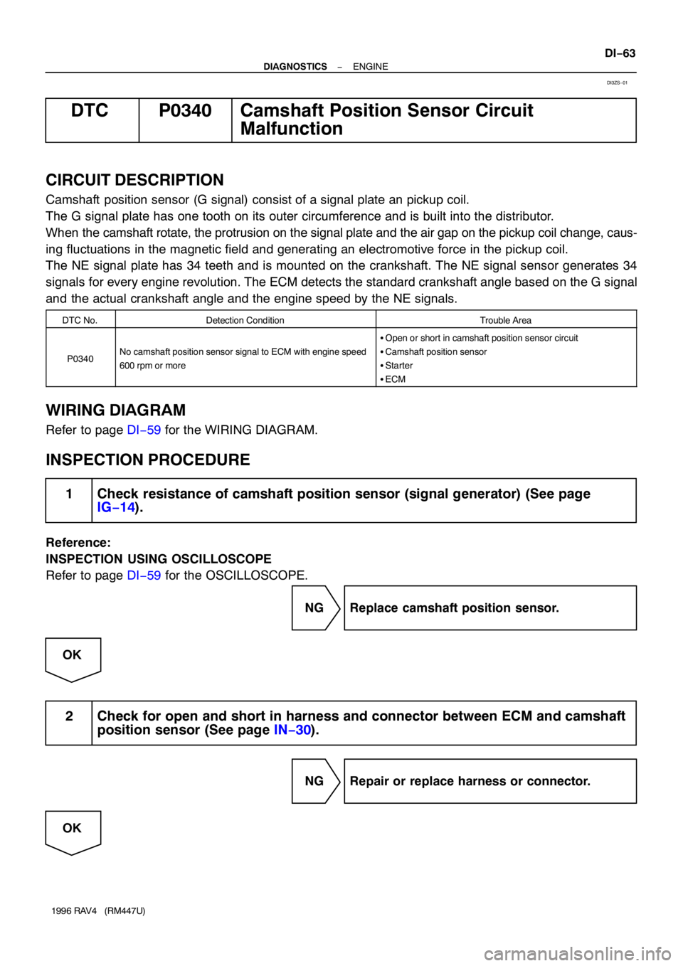
DTC P0340 Camshaft Position Sensor Circuit
Malfunction
CIRCUIT DESCRIPTION
Camshaft position sensor (G signal) consist of a signal plate an pickup coil.
The G signal plate has one tooth on its outer circumference and is built into the distributor.
When the camshaft rotate, the protrusion on the signal plate and the air gap on the pickup coil change, caus-
ing fluctuations in the magnetic field and generating an electromotive force in the pickup coil.
The NE signal plate has 34 teeth and is mounted on the crankshaft. The NE signal sensor generates 34
signals for every engine revolution. The ECM detects the standard crankshaft angle based on the G signal
and the actual crankshaft angle and the engine speed by the NE signals.
DTC No.Detection ConditionTrouble Area
P0340No camshaft position sensor signal to ECM with engine speed
600 rpm or more
�Open or short in camshaft position sensor circuit
�Camshaft position sensor
�Starter
�ECM
WIRING DIAGRAM
Refer to page DI−59 for the WIRING DIAGRAM.
INSPECTION PROCEDURE
1 Check resistance of camshaft position sensor (signal generator) (See page
IG−14).
Reference:
INSPECTION USING OSCILLOSCOPE
Refer to page DI−59 for the OSCILLOSCOPE.
NG Replace camshaft position sensor.
OK
2 Check for open and short in harness and connector between ECM and camshaft
position sensor (See page IN−30).
NG Repair or replace harness or connector.
OK
DI3ZS−01
Page 420 of 1354

S07638
IG1
1H 1DI4I4
E4
E43 20
EA17
IG111
2221
20 8
1412
67
2
W B−WB−RB−R B−W
B−W
B−W
B−W
L−Y 4
53
2
1 Tr2
Igniter To Tachometer Distributor
BatteryFusible Link BlockR/B No.2
B−R IG Switch 4ECM
IGT
IGF5V
Tr1
AM2B
B−Y
Ignition Coil
J/B No.1
MAIN DI−100
− DIAGNOSTICSENGINE
1996 RAV4 (RM447U)
DTC P1300 Igniter Circuit Malfunction
CIRCUIT DESCRIPTION
This ECM determines the ignition timing, turns on Tr1 at a predetermined angle (°CA) before the desired
ignition timing and outputs an ignition signal (IGT) ”1” to the igniter.
Since the width of the IGT signal is constant, the dwell angle control circuit in the igniter determines the time
the control circuit starts primary current flow to the ignition coil based on the engine rpm and ignition timing
one revolution ago, that is, the time the Tr
2 turns on.
When it reaches the ignition timing, the ECM turns Tr
1 off and outputs the IGT signal ”O”.
This turns Tr
2 off, interrupting the primary current flow and generating a high voltage in the secondary coil
which causes the spark plug to spark. Also, by the counter electromotive force generated when the primary
current is interrupted, the igniter sends an ignition confirmation signal (IGF) to the ECM.
The ECM stops fuel injection as a fail safe function when the IGF signal is not input to the ECM.
DTC No.DTC Detecting ConditionTrouble Area
P1300No IGF signal to ECM for 8 consecutive IGT signals during
engine running.�Open or short in IGF or IGT circuit from igniter to ECM
�Igniter
�ECM
WIRING DIAGRAM
DI401−01
Page 668 of 1354

EM−2
− ENGINE MECHANICALCO/HC
1996 RAV4 (RM447U)
6. TROUBLESHOOTING
If the CO/HC concentration does not comply with regulations,
troubleshoot in the order given below.
(a) Check the oxygen sensor operation (See page DI−42).
(b) See the table below for possible causes, then inspect and
correct the applicable causes if necessary.
HCCOProblemsCauses
HighNormalRough idle4. Faulty ignitions:
�Incorrect timing
�Fouled, shorted or improperly gapped plugs
�Open or or crossed high−tension cords
�Cracked distributor cap
5. Incorrect valve clearance
6. Leaky EGR valve
7. Leaky intake and exhaust valves
8. Leaky cylinder
HighLowRough idle
(Fluctuating HC reading)1. Vacuum leaks:
�PCV hose
�EGR valve
�Intake manifold
�Throttle body
�IAC valve
�Brake booster line
2. Lean mixture causing misfire
HighHighRough idle
(Black smoke from exhaust)1. Restricted air filter
2. Faulty SFI system:
�Faulty pressure regulator
�Clogged fuel return line
�Defective ECT sensor
�Defective IAT sensor
�Faulty ECM
�Faulty injector
�Faulty throttle position sensor
�MAP sensor
Page 669 of 1354

EM0EH−03
S01361
Compression
Gauge
− ENGINE MECHANICALCOMPRESSION
EM−3
1996 RAV4 (RM447U)
COMPRESSION
INSPECTION
HINT:
If there is lack of power, excessive oil consumption or poor fuel
economy, measure the compression pressure.
1. WARM UP AND STOP ENGINE
Allow the engine to warm up to normal operating temperature.
2. DISCONNECT DISTRIBUTOR CONNECTOR
3. DISCONNECT HIGH−TENSION CORDS FROM SPARK
PLUGS AND IGNITION COIL
4. REMOVE SPARK PLUGS
5. CHECK CYLINDER COMPRESSION PRESSURE
(a) Insert a compression gauge into the spark plug hole.
(b) Fully open the throttle.
(c) While cranking the engine, measure the compression
pressure.
HINT:
Always use a fully charged battery to obtain engine speed of
250 rpm or more.
(d) Repeat steps (a) through (c) for each cylinder.
NOTICE:
This measurement must be done in as short a time as pos-
sible.
Compression pressure:
1,275 kPa (13.0 kgf/cm
2, 185 psi) or more
Minimum pressure: 932 kPa (9.5 kgf/cm
2, 135 psi)
Difference between each cylinder:
98 kPa (1.0 kgf/cm
2, 14 psi) or less
(e) If the cylinder compression in one or more cylinders is low,
pour a small amount of engine oil into the cylinder through
the spark plug hole and repeat steps (a) through (c) for
cylinders with low compression.
�If adding oil helps the compression, it is likely that
the piston rings and/or cylinder bore are worn or
damaged.
�If pressure stays low, a valve may be sticking or
seating is improper, or there may be leakage past
the gasket.
6. REINSTALL SPARK PLUGS
7. RECONNECT HIGH−TENSION CORDS TO SPARK
PLUGS AND IGNITION COIL
Page 670 of 1354
EM−4
− ENGINE MECHANICALCOMPRESSION
1996 RAV4 (RM447U)
8. RECONNECT DISTRIBUTOR CONNECTOR