Page 125 of 1354
BO3D4−01
BO−28
− BODYFRONT WIPER AND WASHER
1996 RAV4 (RM447U)
INSPECTION
INSPECT FRONT WASHER NOZZLE
While operating the washer, check that the distance between
the point where the washer fluid from the upper nozzles hits the
windshield and the upsurge area are within the range indicated
by the hatched line.
AApprox. 250 mm (9.84 in.)
BApprox. 270 mm (10.6 in.)
CApprox. 370 mm (14.5 in.)
DApprox. 155 mm (6.10 in.)
EApprox. 240 mm (9.44 in.)
FApprox. 200 mm (7.87 in.)
GApprox. 370 mm (14.5 in.)
Page 126 of 1354
BO108−01
BE3367
2 ∼ 2.5 mm
(0.079 ∼ 0.098 in.)
0.7 ∼ 0.75 mm
(0.028 ∼ 0.030 in.)
− BODYFRONT WIPER AND WASHER
BO−29
1996 RAV4 (RM447U)
ADJUSTMENT
ADJUST FRONT WASHER NOZZLE
Using a tool like the one shown in the illustration, change the
direction of the nozzle hole to adjust the point where washer
fluid hits the windshield.
Page 130 of 1354
BO10C−01
H02952
A B
− BODYREAR WIPER AND WASHER
BO−33
1996 RAV4 (RM447U)
ADJUSTMENT
INSPECT REAR WASHER NOZZLE
While operating the washer, check that the point where the
washer fluid hits the back door glass and the upsurge area are
within the range indicated by the circle.
AApprox. 174 mm (6.85 in.)
BApprox. 167 mm (6.57 in.)
Page 798 of 1354
28
G ELECTRICAL WIRING ROUTING
Position of Parts in Engine Compartment
*1 : w/ A/C
*2 : w/o A/C
A 1 A/C Condenser Fan Motor E 1 Electronically Controlled Transmission Solenoid
A 2 A/C Magnetic Clutch and Lock Sensor E 2 Engine Coolant Temp. Sensor
A 3 A/C Triple Pressure SW (A/C Dual and Single
Pressure SW) F 1 Front Side Marker Light LH
A 4 A/C Water Temp. SW F 2 Front Side Marker Light RH
A 5 A/T Fluid Temp. SW F 3 Front Turn Signal Light LH and Front Parking
A 6 ABS Actuator Light LH
A 7 ABS Actuator F 4 Front Turn Signal Light RH and Front Parking
A 8 ABS Relay Light RH
A 9 ABS Relay F 5 Front Washer Motor
A 10 ABS Speed Sensor Front LH F 6 Front Wiper Motor
A 11 ABS Speed Sensor Front RH F 7 Fusible Link Block
B 1 Back-Up Light SW (M/T) G 1 Generator
B 2 Brake Fluid Level Warning SW G 2Generator
C 1 Center Diff. Lock Warning Buzzer SW H 1 Headlight LH
C 2 Crankshaft Position Sensor H 2 Headlight RH
C 3 Cruise Control Actuator H 3 Horn
D 1 Data Link Connector 1
Page 1306 of 1354
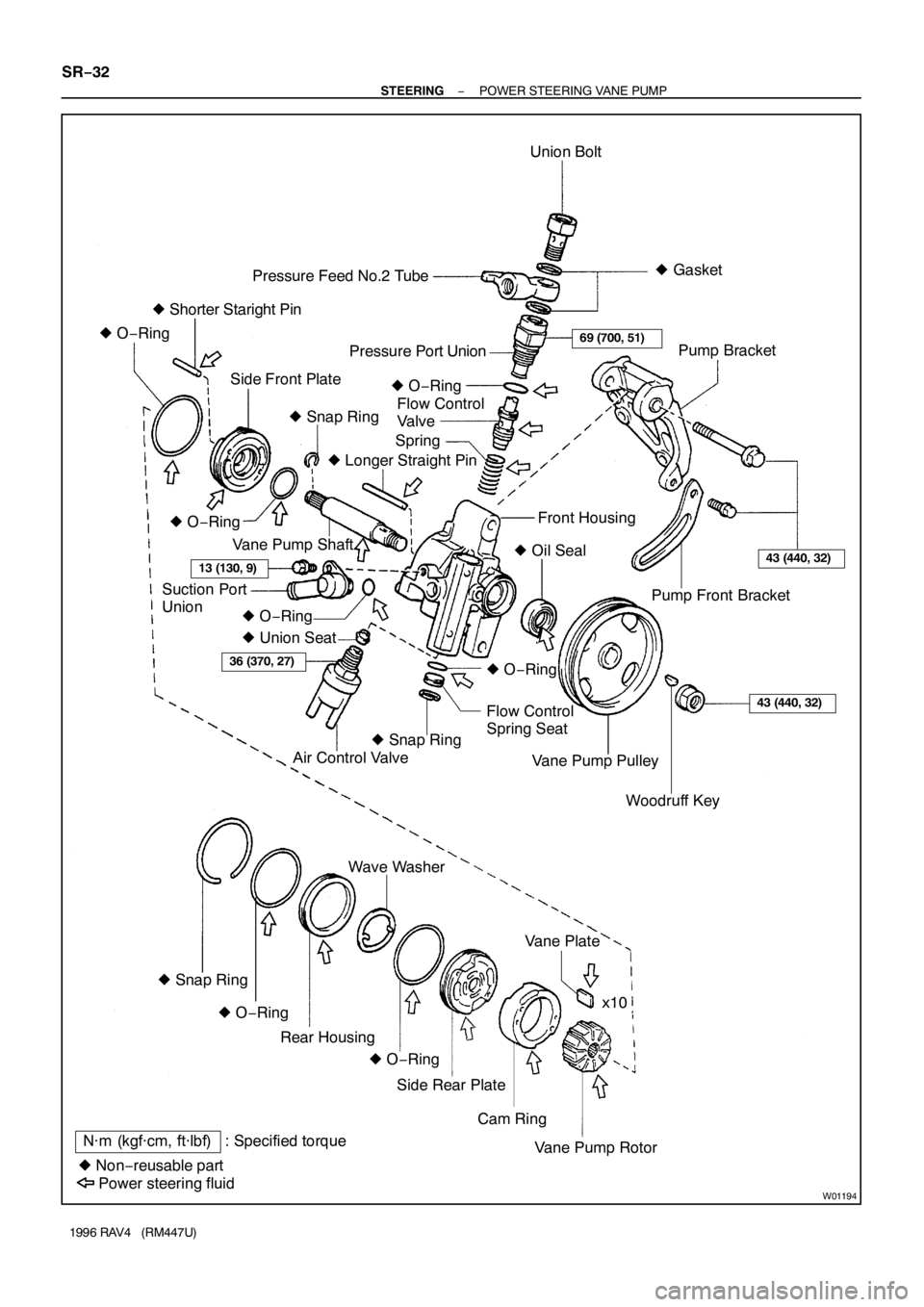
W01194
N·m (kgf·cm, ft·lbf) : Specified torque
� Non−reusable partUnion Bolt
Spring Pressure Feed No.2 Tube
Side Front PlatePressure Port Union
Flow Control
Valve
Pump Front Bracket
Flow Control
Spring Seat� Gasket
� Shorter Staright Pin
Air Control Valve � O−Ring
� Snap Ring� O−Ring
� Union Seat� Longer Straight Pin
Vane Pump Shaft
Suction Port
UnionFront Housing
� O−Ring
� Oil Seal
� O−Ring
� O−Ring
Woodruff Key Vane Pump PulleyPump Bracket
� Snap Ring
Cam Ring Side Rear PlateVane Plate Wave Washer
Vane Pump Rotorx10
Power steering fluidRear Housing
� O−Ring � O−Ring � Snap Ring
69 (700, 51)
13 (130, 9)43 (440, 32)
36 (370, 27)
43 (440, 32)
SR−32
− STEERINGPOWER STEERING VANE PUMP
1996 RAV4 (RM447U)
Page 1314 of 1354

6. INSTALL CAM RING
Align the holes of the cam ring and 2 straight pi")
R11231
Inscribed Mark
R10976
Round End
W01173
Wave Washer
R10968
SR−40
− STEERINGPOWER STEERING VANE PUMP
1996 RAV4 (RM447U)
6. INSTALL CAM RING
Align the holes of the cam ring and 2 straight pins and install the
ring with the inscribed mark facing outward.
7. INSTALL VANE PLATES
Install the 10 plates with the round end facing outward.
8. INSTALL SIDE REAR PLATE
(a) Coat a new O−ring with power steering fluid and install it
to the plate.
(b) Align the holes of the plate and 2 straight pins, and install
the plate.
9. INSTALL WAVE WASHER
Install the washer so that its protrusions fit into the slots in the
side rear plate.
10. INSTALL REAR HOUSING
(a) Coat a new O−ring with power steering fluid and install it
to the housing.
(b) Using a plastic hammer, tap in the housing to the front
housing.
NOTICE:
Be careful not to damage the O−ring.
(c) Install a new snap ring.
11. INSTALL FLOW CONTROL SPRING SEAT
(a) Coat a new O−ring with power steering fluid and install it
to the flow control spring seat.
(b) Install the 2−3 threads of the bolt to the spring seat.
(c) Using pliers, install the spring seat to the front housing.
NOTICE:
�Be careful not to damage the O−ring.
�Make sure to install the seat facing the correct direc-
tion.
Page 1319 of 1354
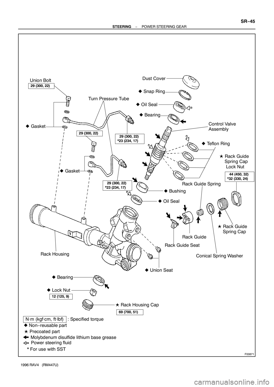
F00871
29 (300, 22)
*23 (234, 17)
� Gasket
29 (300, 22)
*23 (234, 17)
44 (450, 32)
*32 (330, 24)
Union Bolt
� Snap Ring
� Oil Seal Turn Pressure TubeDust Cover
Rack GuideControl Valve
Assembly
� Rack Guide
Spring Cap
Lock Nut � Bearing
� Lock Nut � Gasket
� Oil Seal� Teflon Ring
� Bearing� Union Seat� Bushing
� Precoated part
Molybdenum disulfide lithium base greaseRack Guide Seat� Rack Guide
Spring Cap
� Rack Housing Cap
N·m (kgf·cm, ft·lbf) : Specified torque
* For use with SST � Non−reusable part
Power steering fluid
29 (300, 22)
69 (700, 51)
12 (125, 9)
29 (300, 22)
Rack Housing
Conical Spring Washer
Rack Guide Spring
− STEERINGPOWER STEERING GEAR
SR−45
1996 RAV4 (RM447U)
Page 1320 of 1354
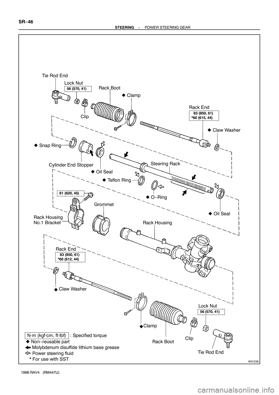
W01239
� Snap Ring
� Oil Seal Tie Rod End
Lock Nut
Rack Boot
Clip
Cylinder End Stopper
Rack Housing � Clamp
� Oil Seal � O−Ring � Teflon RingSteering RackRack End
� Claw Washer
Rack Housing
No.1 BracketGrommet
Lock Nut
Molybdenum disulfide lithium base grease
N·m (kgf·cm, ft·lbf) : Specified torque
* For use with SST � Non−reusable part
Power steering fluid
�
�
56 (570, 41)
61 (620, 45)
56 (570, 41)
83 (850, 61)
*60 (615, 44)
83 (850, 61)
*60 (612, 44)
Rack End
Claw Washer
Clamp
Rack BootClip
Tie Rod End SR−46
− STEERINGPOWER STEERING GEAR
1996 RAV4 (RM447U)

INSPECTION
INSPECT FRONT WASHER NOZZLE
While operating the washer, check that the distance between
the point where the washer flu")

0.7 ∼ 0.75 mm
(0.028 ∼ 0.030 in.)
− BODYFRONT WIPER AND WASHER
BO−29
1996 RAV4 (RM447U)
ADJUSTMENT
ADJUST FRONT WASHER NOZZLE
Using a too")

ADJUSTMENT
INSPECT REAR WASHER NOZZLE
While operating the washer, check that the point where the
washer fluid hits the")