Page 5 of 1354

AX0T6−02
Q05259
Q05234
Q06417
Q06418
− AUTOMATIC TRANSAXLE (A241E)VALVE BODY ASSEMBLY
AX−5
1996 RAV4 (RM447U)
VALVE BODY ASSEMBLY
ON−VEHICLE REPAIR
1. REMOVE DRAIN PLUG AND DRAIN ATF
2. REMOVE OIL PAN AND GASKET
Remove the 18 bolts.
NOTICE:
Some fluid will remain in the oil pan. Remove all pan bolts,
and carefully remove the oil pan assembly. Discard the
gasket.
3. EXAMINE PARTICLES IN PAN
Remove the magnets and use them to collect any steel chips.
Look carefully at the chips and particles in the pan and the mag-
net to anticipate what type of wear you will find in the transaxle.
�Steel (magnetic): bearing, gear and plate wear
�Brass (non−magnetic): bearing wear
4. REMOVE OIL STRAINER AND APPLY PIPE BRACKET
NOTICE:
Be careful as some fluid will come out with the oil strainer.
(a) Remove the 3 bolts, oil strainer and gasket.
(b) Remove the 2 bolts and apply pipe bracket.
5. REMOVE OIL PIPE CLAMP AND OIL PIPES
(a) Remove the bolt and oil pipe clamp.
(b) Pry up the both pipe ends with a large screwdriver and re-
move the 5 pipes.
NOTICE:
Be careful not to bend or damage the pipe.
Page 8 of 1354
Q06417
Q05234
Q05259
AX−8
− AUTOMATIC TRANSAXLE (A241E)VALVE BODY ASSEMBLY
1996 RAV4 (RM447U)
15. INSTALL OIL STRAINER AND APPLY PIPE BRACKET
Install the oil strainer, gasket with the 3 bolts.
Torque: 10 N·m (102 kgf·cm, 7 ft·lbf)
HINT:
Replace used the gasket with a new one.
16. INSTALL 2 MAGNETS IN OIL PAN
17. INSTALL OIL PAN AND GASKET
(a) Install a new gasket to the oil pan.
(b) Install the oil pan with the 18 bolts.
Torque: 4.9 N·m (50 kgf·cm, 43 in.·lbf)
18. INSTALL DRAIN PLUG
Torque: 17 N·m (175 kgf·cm, 13 ft·lbf)
19. FILL ATF AND CHECK ATF (See page DI−127)
Page 16 of 1354

Q08764
Q08765
Q08766
Q08767
AX−16
− AUTOMATIC TRANSAXLE (A241E)AUTOMATIC TRANSAXLE UNIT
1996 RAV4 (RM447U)
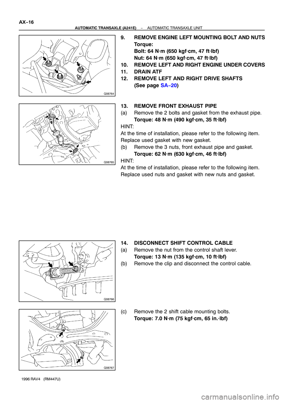
9. REMOVE ENGINE LEFT MOUNTING BOLT AND NUTS
Torque:
Bolt: 64 N·m (650 kgf·cm, 47 ft·lbf)
Nut: 64 N·m (650 kgf·cm, 47 ft·lbf)
10. REMOVE LEFT AND RIGHT ENGINE UNDER COVERS
11. DRAIN ATF
12. REMOVE LEFT AND RIGHT DRIVE SHAFTS
(See page SA−20)
13. REMOVE FRONT EXHAUST PIPE
(a) Remove the 2 bolts and gasket from the exhaust pipe.
Torque: 48 N·m (490 kgf·cm, 35 ft·lbf)
HINT:
At the time of installation, please refer to the following item.
Replace used gasket with new gasket.
(b) Remove the 3 nuts, front exhaust pipe and gasket.
Torque: 62 N·m (630 kgf·cm, 46 ft·lbf)
HINT:
At the time of installation, please refer to the following item.
Replace used nuts and gasket with new nuts and gasket.
14. DISCONNECT SHIFT CONTROL CABLE
(a) Remove the nut from the control shaft lever.
Torque: 13 N·m (135 kgf·cm, 10 ft·lbf)
(b) Remove the clip and disconnect the control cable.
(c) Remove the 2 shift cable mounting bolts.
Torque: 7.0 N·m (75 kgf·cm, 65 in.·lbf)
Page 29 of 1354
Q06064
AX129−01
AT0103
D00691
D00692
AX−8
− AUTOMATIC TRANSAXLE (A540H)VALVE BODY ASSEMBLY
1996 RAV4 (RM447U)
VALVE BODY ASSEMBLY
ON−VEHICLE REPAIR
1. REMOVE NO.2 ENGINE UNDER COVER
2. DRAIN ATF
Using a 10 mm hexagon wrench, remove the drain plug, and
drain the ATF into a suitable container.
3. REMOVE OIL PAN AND GASKET
(a) Remove the 17 bolts.
(b) Remove the oil pan by lifting transaxle case.
NOTICE:
Some fluid remain in the oil pan.
4. EXHAUST PARTICLES IN PAN
Remove the magnet and use it to collect any steel chips.
Lock carefully at the chips and particles in the oil pan and on the
magnet to anticipate when type of wear you will find in the trans-
axle.
�Steel (magnetic): bearing, gear and plate wear
�Brass (non−magnetic): bushing wear
5. REMOVE OIL PIPE BRACKET AND STRAINER
(a) Remove the 2 bolts and oil pipe bracket.
(b) Remove the 3 bolts and strainer.
(c) Remove the gasket from the strainer.
6. REMOVE MANUAL VALVE BODY
(a) Remove the 2 bolts and detent spring.
Page 33 of 1354

Z13390A B
Z13391
A
BA
B
Q06019
Q06064
AX−12
− AUTOMATIC TRANSAXLE (A540H)VALVE BODY ASSEMBLY
1996 RAV4 (RM447U)
(d) Place the detent springs on the manual valve body and
hand−tighten the 2 bolts first.
Then, tighten them with a torque wrench.
Torque: 11 N·m (110 kgf·cm, 8 ft·lbf)
HINT:
Each bolt length is indicated below.
Bolt length:
Bolt A: 14 mm (0.55 in.)
Bolt B: 37 mm (1.46 in.)
(e) Check that the manual valve lever is touching the center
of the detent spring tip roller.
18. INSTALL PIPE BRACKET AND OIL STRAINER
Torque: 11 N·m (110 kgf·cm, 8 ft·lbf)
HINT:
Each bolt length is indicated below.
Bolt length:
Bolt A: 22 mm (0.87 in.)
Bolt B: 53 mm (2.09 in.)
19. INSTALL MAGNETS IN PLACE
NOTICE:
Make sure that the magnets do not interfere with the oil
pipes.
20. INSTALL OIL PAN WITH NEW GASKET
(a) Install a new gasket and oil pan.
(b) Install and tighten 17 bolts.
Torque: 7.9 N·m (80 kgf·cm, 70 in.·lbf)
21. FILL ATF AND CHECK FLUID LEVEL
(a) Using a 10 mm hexagon wrench, install a new gasket and
the drain plug.
Torque: 49 N·m (500 kgf·cm, 36 ft·lbf)
(b) Fill the ATF and check the fluid level (See page DI−173).
22. INSTALL NO.2 ENGINE UNDER COVER
Page 183 of 1354
BR0M5−01
R10630
BR−24
− BRAKEFRONT BRAKE CALIPER
1996 RAV4 (RM447U)
REMOVAL
1. DISCONNECT FLEXIBLE HOSE
(a) Remove the union bolt and 2 gaskets from the caliper,
then disconnect the flexible hose from the caliper.
Torque: 30 N·m (310 kgf·cm, 22 ft·lbf)
HINT:
At the time of installation, please refer to the following item.
Install the flexible hose lock securely in the lock hole in the cali-
per.
(b) Use a container to catch the brake fluid as it drains out.
2. REMOVE CALIPER
(a) Hold the sliding pin and loosen the 2 installation bolts.
Torque: 26 N·m (270 kgf·cm, 20 ft·lbf)
(b) Remove the 2 installation bolts.
(c) Remove the caliper from the torque plate.
3. REMOVE THESE PARTS:
�2 brake pads with anti−squeal shims
�4 pad support plates
Page 300 of 1354
CO0BG−02
S01613
P15462
P15546
1
3
2
P15463
Disconnect
− COOLINGWATER PUMP
CO−5
1996 RAV4 (RM447U)
REMOVAL
1. REMOVE RH ENGINE UNDER COVER
2. DRAIN ENGINE COOLANT
3. REMOVE TIMING BELT (See page EM−15)
4. DISCONNECT LOWER RADIATOR HOSE FROM
WATER INLET
5. REMOVE TIMING BELT TENSION SPRING AND NO.2
IDLER PULLEY
6. REMOVE GENERATOR DRIVE BELT ADJUSTING
BAR
(a) Disconnect the crankshaft position sensor connector
clamp.
(b) Remove the bolt and adjusting bar.
7. REMOVE WATER PUMP AND WATER PUMP COVER
ASSEMBLY
(a) Remove the 2 nuts holding the water pump to the water
bypass pipe.
(b) Remove the 3 bolts in the sequence shown.
(c) Disconnect the water pump cover from the water bypass
pipe, and remove the water pump and water pump cover
assembly.
(d) Remove the gasket and 2 O−ring from the water pump
and water bypass pipe.
Page 311 of 1354

CO0BQ−03
S01355
S01278
w/ A/C
S01293
CO−16
− COOLINGRADIATOR
1996 RAV4 (RM447U)
REMOVAL
1. REMOVE ENGINE UNDER COVERS
2. DRAIN ENGINE COOLANT
3. w/ A/C:
REMOVE COOLER CONDENSER (See page AC−47)
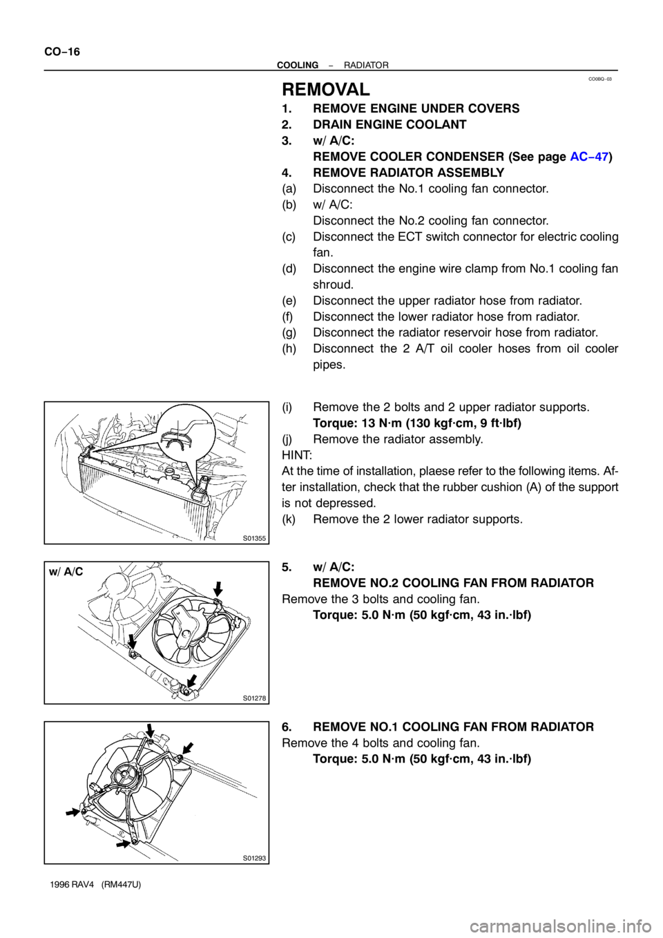
4. REMOVE RADIATOR ASSEMBLY
(a) Disconnect the No.1 cooling fan connector.
(b) w/ A/C:
Disconnect the No.2 cooling fan connector.
(c) Disconnect the ECT switch connector for electric cooling
fan.
(d) Disconnect the engine wire clamp from No.1 cooling fan
shroud.
(e) Disconnect the upper radiator hose from radiator.
(f) Disconnect the lower radiator hose from radiator.
(g) Disconnect the radiator reservoir hose from radiator.
(h) Disconnect the 2 A/T oil cooler hoses from oil cooler
pipes.
(i) Remove the 2 bolts and 2 upper radiator supports.
Torque: 13 N·m (130 kgf·cm, 9 ft·lbf)
(j) Remove the radiator assembly.
HINT:
At the time of installation, plaese refer to the following items. Af-
ter installation, check that the rubber cushion (A) of the support
is not depressed.
(k) Remove the 2 lower radiator supports.
5. w/ A/C:
REMOVE NO.2 COOLING FAN FROM RADIATOR
Remove the 3 bolts and cooling fan.
Torque: 5.0 N·m (50 kgf·cm, 43 in.·lbf)
6. REMOVE NO.1 COOLING FAN FROM RADIATOR
Remove the 4 bolts and cooling fan.
Torque: 5.0 N·m (50 kgf·cm, 43 in.·lbf)