Page 7 of 1354
AT3327
Z11664
B A
B
B A
B A
A A C
AT8586
AT8584
Q06418
− AUTOMATIC TRANSAXLE (A241E)VALVE BODY ASSEMBLY
AX−7
1996 RAV4 (RM447U)
11. INSTALL VALVE BODY
(a) Install the valve body.
(b) Connect the manual valve connecting rod.
(c) Install the 17 bolts and wire retainer.
Bolt length:
Bolt A: 20 mm (0.79 in.)
Bolt B: 30 mm (1.18 in.)
Bolt C: 55 mm (2.17 in.)
Torque: 10 N·m (100 kgf·cm, 7 ft·lbf)
(d) Connect the throttle cable.
12. CONNECT 3 SOLENOID CONNECTORS
13. INSTALL MANUAL DETENT SPRING
Install the manual detent spring with the bolt.
Torque: 10 N·m (100 kgf·cm, 7 ft·lbf)
HINT:
Check that the manual valve lever is in contact with the center
of the roller at the tip of the detent spring.
14. INSTALL OIL PIPE CLAMP AND OIL PIPES
(a) Install the 5 pipes with a large screwdriver.
(b) Install the oil pump clamp with the bolt.
Torque: 10 N·m (100 kgf·cm, 7 ft·lbf)
Page 8 of 1354
Q06417
Q05234
Q05259
AX−8
− AUTOMATIC TRANSAXLE (A241E)VALVE BODY ASSEMBLY
1996 RAV4 (RM447U)
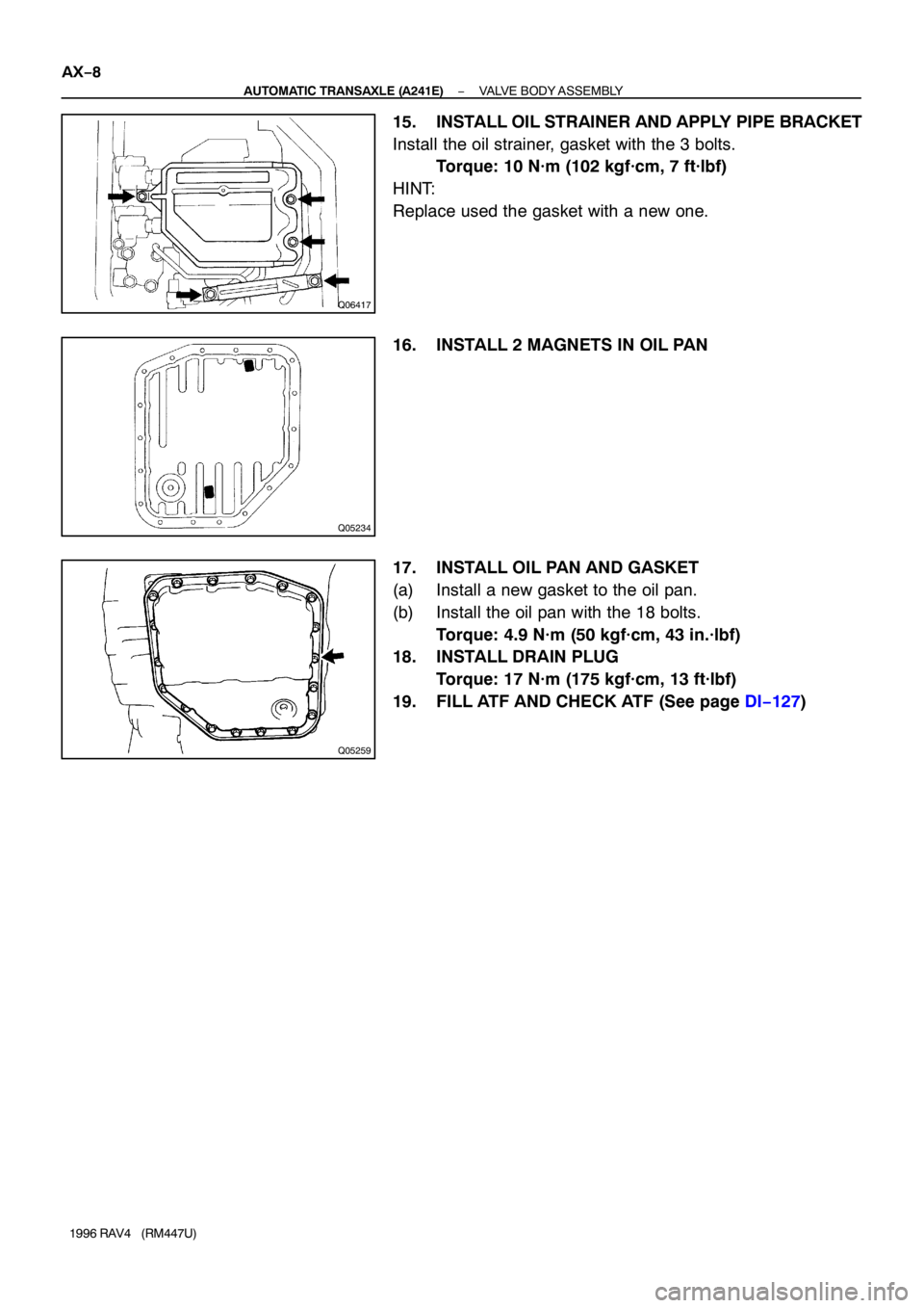
15. INSTALL OIL STRAINER AND APPLY PIPE BRACKET
Install the oil strainer, gasket with the 3 bolts.
Torque: 10 N·m (102 kgf·cm, 7 ft·lbf)
HINT:
Replace used the gasket with a new one.
16. INSTALL 2 MAGNETS IN OIL PAN
17. INSTALL OIL PAN AND GASKET
(a) Install a new gasket to the oil pan.
(b) Install the oil pan with the 18 bolts.
Torque: 4.9 N·m (50 kgf·cm, 43 in.·lbf)
18. INSTALL DRAIN PLUG
Torque: 17 N·m (175 kgf·cm, 13 ft·lbf)
19. FILL ATF AND CHECK ATF (See page DI−127)
Page 10 of 1354
AX056−03
Z02840
SST
Z02841
SST LH Side
Z02842
SST
AX−10
− AUTOMATIC TRANSAXLE (A241E)DIFFERENTIAL OIL SEAL
1996 RAV4 (RM447U)
DIFFERENTIAL OIL SEAL
ON−VEHICLE REPAIR
1. DRAIN ATF
2. REMOVE ENGINE UNDER COVER
3. REMOVE LH AND RH DRIVE SHAFTS
(See page SA−20)
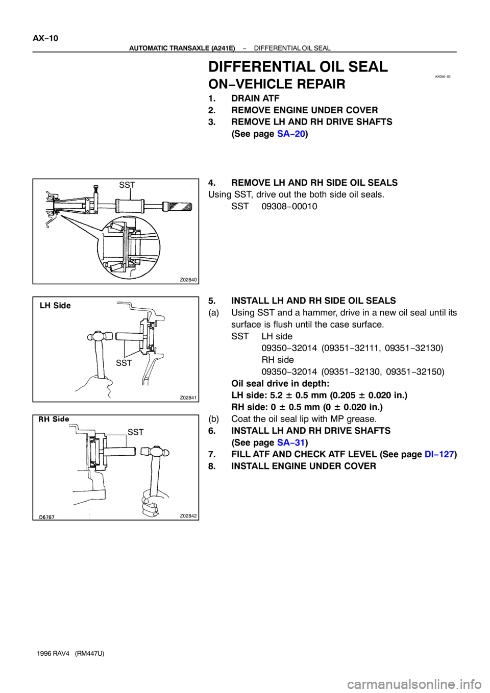
4. REMOVE LH AND RH SIDE OIL SEALS
Using SST, drive out the both side oil seals.
SST 09308−00010
5. INSTALL LH AND RH SIDE OIL SEALS
(a) Using SST and a hammer, drive in a new oil seal until its
surface is flush until the case surface.
SST LH side
09350−32014 (09351−32111, 09351−32130)
RH side
09350−32014 (09351−32130, 09351−32150)
Oil seal drive in depth:
LH side: 5.2 ± 0.5 mm (0.205 ± 0.020 in.)
RH side: 0 ± 0.5 mm (0 ± 0.020 in.)
(b) Coat the oil seal lip with MP grease.
6. INSTALL LH AND RH DRIVE SHAFTS
(See page SA−31)
7. FILL ATF AND CHECK ATF LEVEL (See page DI−127)
8. INSTALL ENGINE UNDER COVER
Page 33 of 1354
Z13390A B
Z13391
A
BA
B
Q06019
Q06064
AX−12
− AUTOMATIC TRANSAXLE (A540H)VALVE BODY ASSEMBLY
1996 RAV4 (RM447U)
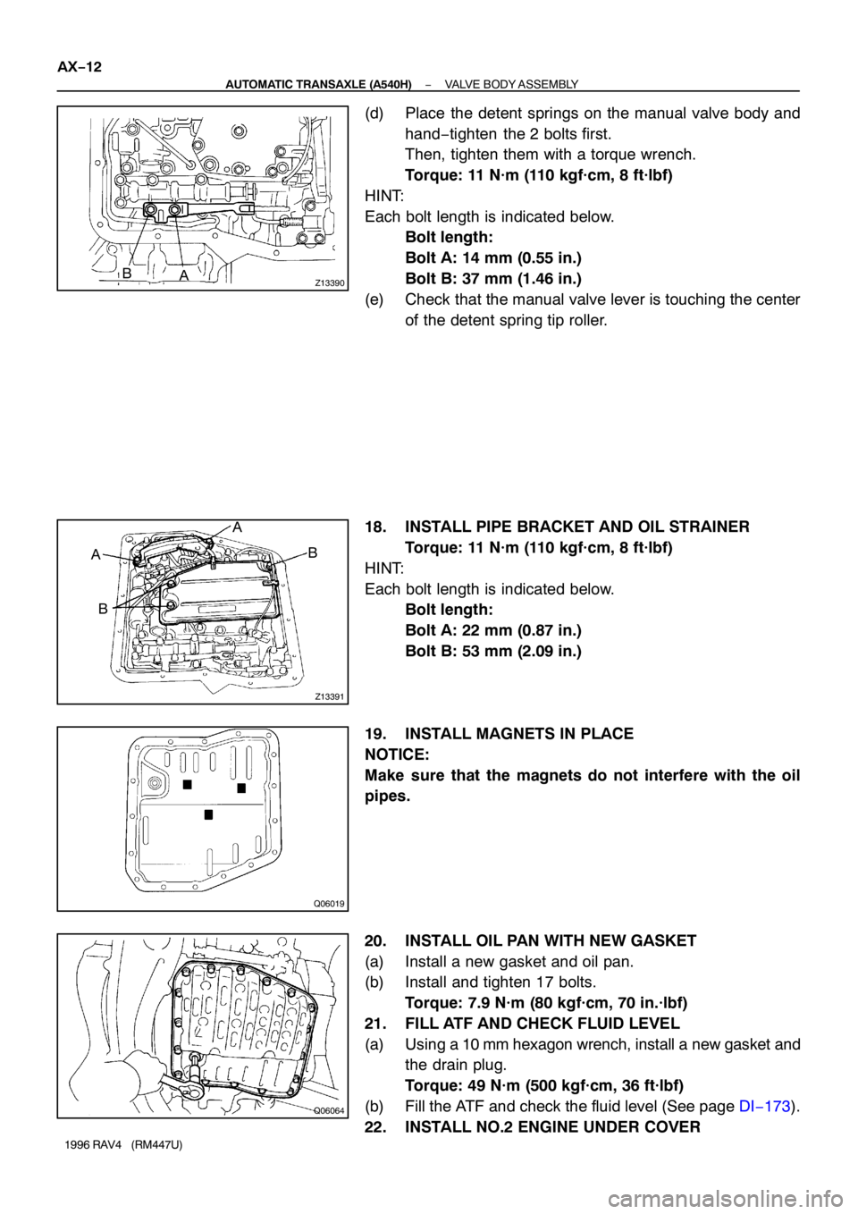
(d) Place the detent springs on the manual valve body and
hand−tighten the 2 bolts first.
Then, tighten them with a torque wrench.
Torque: 11 N·m (110 kgf·cm, 8 ft·lbf)
HINT:
Each bolt length is indicated below.
Bolt length:
Bolt A: 14 mm (0.55 in.)
Bolt B: 37 mm (1.46 in.)
(e) Check that the manual valve lever is touching the center
of the detent spring tip roller.
18. INSTALL PIPE BRACKET AND OIL STRAINER
Torque: 11 N·m (110 kgf·cm, 8 ft·lbf)
HINT:
Each bolt length is indicated below.
Bolt length:
Bolt A: 22 mm (0.87 in.)
Bolt B: 53 mm (2.09 in.)
19. INSTALL MAGNETS IN PLACE
NOTICE:
Make sure that the magnets do not interfere with the oil
pipes.
20. INSTALL OIL PAN WITH NEW GASKET
(a) Install a new gasket and oil pan.
(b) Install and tighten 17 bolts.
Torque: 7.9 N·m (80 kgf·cm, 70 in.·lbf)
21. FILL ATF AND CHECK FLUID LEVEL
(a) Using a 10 mm hexagon wrench, install a new gasket and
the drain plug.
Torque: 49 N·m (500 kgf·cm, 36 ft·lbf)
(b) Fill the ATF and check the fluid level (See page DI−173).
22. INSTALL NO.2 ENGINE UNDER COVER
Page 35 of 1354
Q06041
SST
AX04S−01
Q06072
Q06040SST
Q06042
SST AX−14
− AUTOMATIC TRANSAXLE (A540H)SIDE GEAR SHAFT OIL SEAL
1996 RAV4 (RM447U)
SIDE GEAR SHAFT OIL SEAL
ON−VEHICLE REPAIR
1. REMOVE BOTH DRIVE SHAFTS
(See page SA−20)
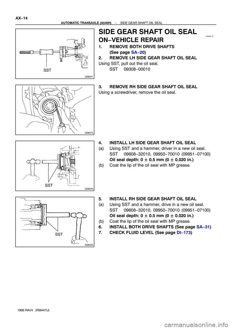
2. REMOVE LH SIDE GEAR SHAFT OIL SEAL
Using SST, pull out the oil seal.
SST 09308−00010
3. REMOVE RH SIDE GEAR SHAFT OIL SEAL
Using a screwdriver, remove the oil seal.
4. INSTALL LH SIDE GEAR SHAFT OIL SEAL
(a) Using SST and a hammer, driver in a new oil seal.
SST 09608−32010, 09950−70010 (09951−07100)
Oil seal depth: 0 ± 0.5 mm (0 ± 0.020 in.)
(b) Coat the lip of the oil seal with MP grease.
5. INSTALL RH SIDE GEAR SHAFT OIL SEAL
(a) Using SST and a hammer, drive in a new oil seal.
SST 09608−32010, 09950−70010 (09951−07100)
Oil seal depth: 0 ± 0.5 mm (0 ± 0.020 in.)
(b) Coat the lip of the oil seal with MP grease.
6. INSTALL BOTH DRIVE SHAFTS (See page SA−31)
7. CHECK FLUID LEVEL (See page DI−173)
Page 64 of 1354

N11726
4
N117274
N11728
1 42
I01272
2
1
BE−32
− BODY ELECTRICALWIPER AND WASHER SYSTEM
1996 RAV4 (RM447U)
9. INSPECT REAR WIPER MOTOR OPERATION
(a) Connect the positive (+) lead from the battery to terminal
4 and the negative (−) lead to the motor body, check that
the motor operates.
If operation is not as specified, replace the motor.
(b) Operate the motor and stop the motor operation any-
where except at the stop position by disconnecting the
positive (+) lead from terminal 4.
(c) Connect terminals 2 and 4.
(d) Connect the positive (+) lead from the battery to terminal
1 and the negative (−) lead to the motor body, check that
the motor stops running at the stop position after the mo-
tor operates again.
If operation is not as specified, replace the motor.
10. INSPECT WASHER MOTOR OPERATION
Connect the positive (+) lead from the battery to terminal 2 and
the negative (−) lead to terminal 1, check that the motor oper-
ates.
NOTICE:
These tests must be performed quickly (within 20 seconds)
to prevent the coil from burning out.
If operation is not as specified, replace the motor.
Page 161 of 1354
BR02G−04
BR−2
− BRAKETROUBLESHOOTING
1996 RAV4 (RM447U)
TROUBLESHOOTING
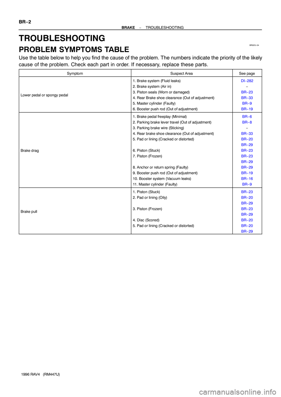
PROBLEM SYMPTOMS TABLE
Use the table below to help you find the cause of the problem. The numbers indicate the priority of the likely
cause of the problem. Check each part in order. If necessary, replace these parts.
SymptomSuspect AreaSee page
Lower pedal or spongy pedal
1. Brake system (Fluid leaks)
2. Brake system (Air in)
3. Piston seals (Worn or damaged)
4. Rear Brake shoe clearance (Out of adjustment)
5. Master cylinder (Faulty)
6. Booster push rod (Out of adjustment)DI−282
−
BR−23
BR−33
BR−9
BR−19
Brake drag
1. Brake pedal freeplay (Minimal)
2. Parking brake lever travel (Out of adjustment)
3. Parking brake wire (Sticking)
4. Rear brake shoe clearance (Out of adjustment)
5. Pad or lining (Cracked or distorted)
6. Piston (Stuck)
7. Piston (Frozen)
8. Anchor or return spring (Faulty)
9. Booster push rod (Out of adjustment)
10. Booster system (Vacuum leaks)
11. Master cylinder (Faulty)BR−6
BR−8
−
BR−33
BR−20
BR−29
BR−23
BR−23
BR−29
BR−29
BR−19
BR−16
BR−9
Brake pull
1. Piston (Stuck)
2. Pad or lining (Oily)
3. Piston (Frozen)
4. Disc (Scored)
5. Pad or lining (Cracked or distorted)BR−23
BR−20
BR−29
BR−23
BR−29
BR−20
BR−20
BR−29
Page 181 of 1354
R10629
BR−22
− BRAKEFRONT BRAKE PAD
1996 RAV4 (RM447U)
7. INSTALL NEW PADS
NOTICE:
When replacing worn pads, the anti−squeal shims must be
replaced together with the pads.
(a) Apply disc brake grease to both side of the inner anti−
squeal shims (See page BR−20).
(b) Install the anti−squeal shim to the inner pad.
(c) Install the inner pad with pad wear indicator plate facing
upward.
(d) Install the outer pad.
NOTICE:
There should be no oil or grease adhering to the friction
surfaces of the pads or the disc.
8. INSTALL CALIPER
(a) Draw out a small amount of brake fluid from the reservoir.
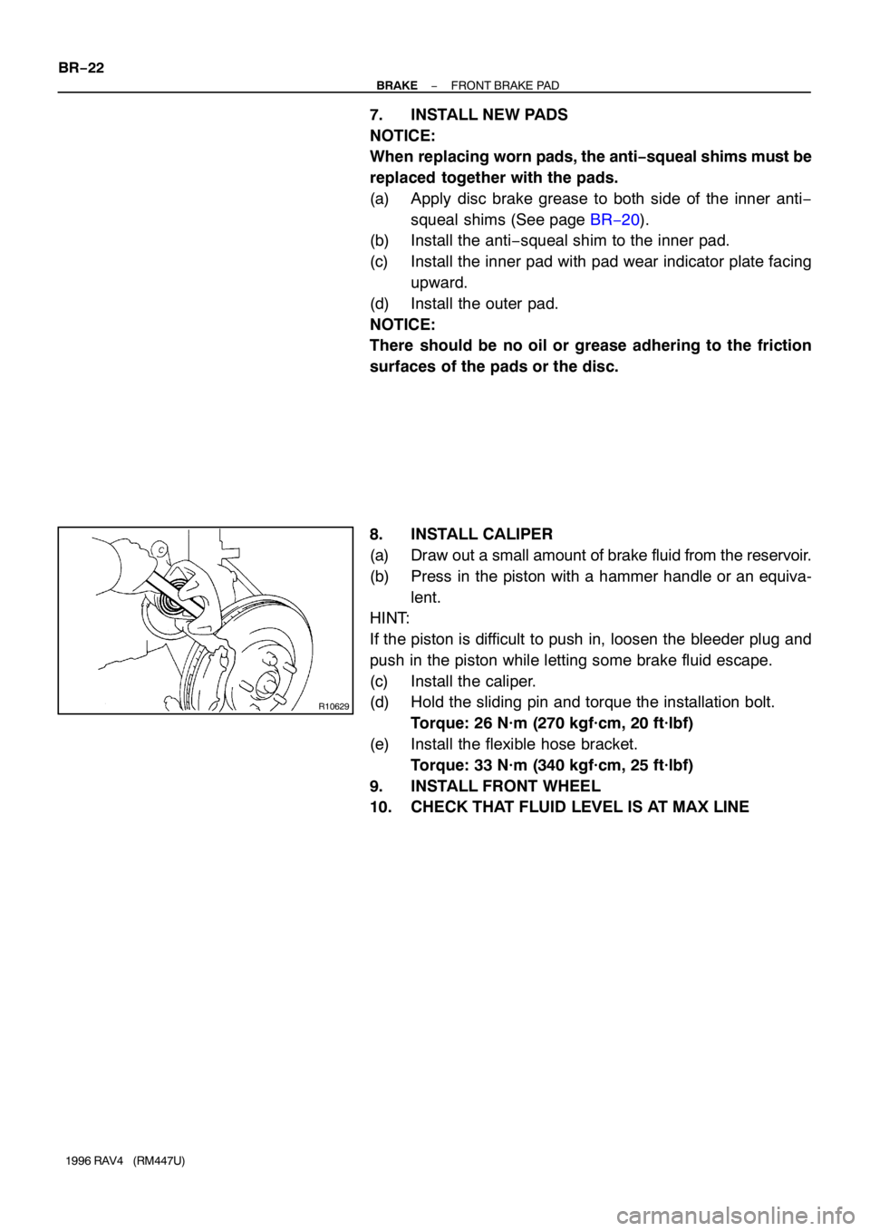
(b) Press in the piston with a hammer handle or an equiva-
lent.
HINT:
If the piston is difficult to push in, loosen the bleeder plug and
push in the piston while letting some brake fluid escape.
(c) Install the caliper.
(d) Hold the sliding pin and torque the installation bolt.
Torque: 26 N·m (270 kgf·cm, 20 ft·lbf)
(e) Install the flexible hose bracket.
Torque: 33 N·m (340 kgf·cm, 25 ft·lbf)
9. INSTALL FRONT WHEEL
10. CHECK THAT FLUID LEVEL IS AT MAX LINE