Page 699 of 1354

EM1B8−02
S01285
S01557
− ENGINE MECHANICALCYLINDER HEAD
EM−33
1996 RAV4 (RM447U)
REMOVAL
1. REMOVE RH ENGINE UNDER COVER
2. DRAIN ENGINE COOLANT
3. A/T only:
DISCONNECT THROTTLE CABLE FROM THROTTLE
BODY
4. DISCONNECT ACCELERATOR CABLE FROM
THROTTLE BODY
5. REMOVE AIR CLEANER CAP AND CASE
6. REMOVE GENERATOR (See page CH−7)
7. REMOVE DISTRIBUTOR
8. REMOVE FRONT EXHAUST PIPE
(a) Using a 14 mm deep socket wrench, remove the 3 nuts
holding the front exhaust pipe to the front TWC.
(b) Remove the 2 bolts holding the front exhaust pipe to the
TWC w/ pipe.
(c) Remove the front exhaust pipe and 2 gaskets.
9. REMOVE EXHAUST MANIFOLD AND HEAT INSULA-
TOR ASSEMBLY
(a) Disconnect the oxygen sensor (bank 1 sensor 1) connec-
tor.
(b) Disconnect the oxygen sensor (bank 1 sensor 2) connec-
tor.
(c) Remove the 6 bolts and manifold upper heat insulator.
(d) Remove the 2 bolts holding the RH exhaust manifold stay
to the cylinder block.
(e) Remove the 6 nuts, the exhaust manifold and heat insula-
tor assembly.
Page 786 of 1354

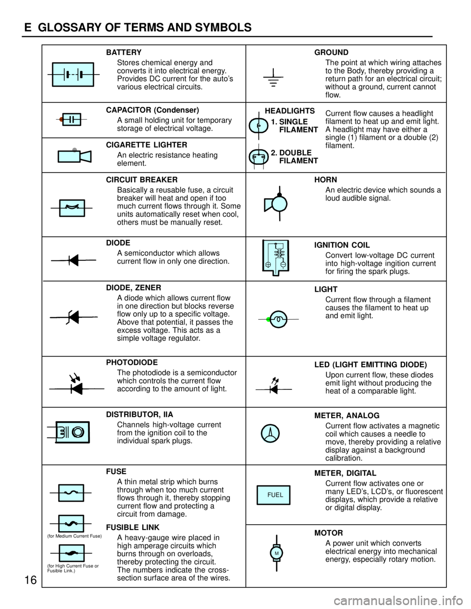
METER, ANALOG
Current flow activates a magnetic
coil which causes a needle to
move, thereby providing a relative
display against a background
calibration. LED (LIGHT EMITTING DIODE)
Upon current flow, these diodes
emit light without producing the
heat of a comparable light. IGNITION COIL
Convert low-voltage DC current
into high-voltage ingition current
for firing the spark plugs. 1. SINGLE
FILAMENT
GROUND
The point at which wiring attaches
to the Body, thereby providing a
return path for an electrical circuit;
without a ground, current cannot
flow.
Current flow causes a headlight
filament to heat up and emit light.
A headlight may have either a
single (1) filament or a double (2)
filament. BATTERY
Stores chemical energy and
converts it into electrical energy.
Provides DC current for the auto's
various electrical circuits.
CAPACITOR (Condenser)
A small holding unit for temporary
storage of electrical voltage.
CIRCUIT BREAKER
Basically a reusable fuse, a circuit
breaker will heat and open if too
much current flows through it. Some
units automatically reset when cool,
others must be manually reset.
DIODE
A semiconductor which allows
current flow in only one direction.
DIODE, ZENER
A diode which allows current flow
in one direction but blocks reverse
flow only up to a specific voltage.
Above that potential, it passes the
excess voltage. This acts as a
simple voltage regulator.
PHOTODIODE
The photodiode is a semiconductor
which controls the current flow
according to the amount of light.
FUSE
A thin metal strip which burns
through when too much current
flows through it, thereby stopping
current flow and protecting a
circuit from damage.
FUSIBLE LINK
A heavy-gauge wire placed in
high amperage circuits which
burns through on overloads,
thereby protecting the circuit.
The numbers indicate the cross-
section surface area of the wires.HORN
An electric device which sounds a
loud audible signal.
LIGHT
Current flow through a filament
causes the filament to heat up
and emit light.
METER, DIGITAL
Current flow activates one or
many LED's, LCD's, or fluorescent
displays, which provide a relative
or digital display.
MOTOR
A power unit which converts
electrical energy into mechanical
energy, especially rotary motion. CIGARETTE LIGHTER
An electric resistance heating
element.
DISTRIBUTOR, IIA
Channels high-voltage current
from the ignition coil to the
individual spark plugs.2. DOUBLE
FILAMENT HEADLIGHTS
FUEL
(for High Current Fuse or
Fusible Link.)
(for Medium Current Fuse)
M
16
E GLOSSARY OF TERMS AND SYMBOLS
Page 799 of 1354
29
G
Position of Parts in Engine Compartment
I 1 Idle Air Control Valve R 1Radiator Fan Motor
I 2 Igniter R 2 Rear Washer Motor
I 3 Ignition Coil and Distributor
I 4 Ignition Coil and Distributor S 1 Solenoid Valve SLD
I 5 Injector No. 1 S 2 Starter
I 6 Injector No. 2 S 3 Starter
I 7 Injector No. 3
I 8 Injector No. 4 T 1 Throttle Position Sensor
I 9 Intake Air Temp. Sensor
V 1 Vapor Pressure Sensor
K 1 Knock Sensor V 2 Vehicle Speed Sensor (Combination Meter)
V 3 Vehicle Speed Sensor (Front)
M 1 Manifold Absolute Pressure Sensor V 4 Vehicle Speed Sensor (Rear)
V 5 VSV (Center Diff. Lock No. 1)
N 1 Noise Filter (Ignition System) V 6 VSV (Center Diff. Lock No. 2)
V 7 VSV (EGR)
O 1 Oil Pressure SW V 8 VSV (EVAP)
O 2 Oxygen Sensor (Bank 1 Sensor 1) V 9 VSV (Vapor Pressure Sensor)
O 3 Oxygen Sensor (Bank 1 Sensor 2)
W 1 Water Temp. Sender
P 1 Park/Neutral Position SW (A/T)
Page 829 of 1354
60
IGNITION
IG 1 11
IG 1 4
20A
AM2
2 2
A
ECJ 2
JUNC
CON21 4 EA1 7
B-R B-R B-R
B-Y B- O
B-W W
B
L- YG
B- W B-O B
B-O
DISTRIBUTOR
BATTERYIGNITION
COIL
BR
B
A 2A1 G- G+ B1
B2 IGNITION COIL AND DISTRIBUTORB I 3 , I 4
A
20 21
2
E
OCK
A
B-O
I 5
W
I 4
(
SHIELDED)
(
SHIELDED)
AIG 2 8
4
NCTION
ONNECTOR
B TO TA C H
[C O M B .
TO A/C AM PRIFIER
1 2
CRANKSH
POSITION
SENSOR C 2
R
1D 8
1H 14
CB
IG T IGF EXT 53
IG N ITER I 2
AFT
TIO N
NECTORNE- IGT IGF
E 4
ENGINE CONTROL
MODULEG+ NE+
R
417 5 20 3J
BB
OM ETER
METER]G
IG NITION S W I1 0 AM1ACC
IG 1
76AM2 IG2
ST2
80A M AIN
FUSIBL
LINK BL F 7
U
DJ
C
DD
Page 837 of 1354

68
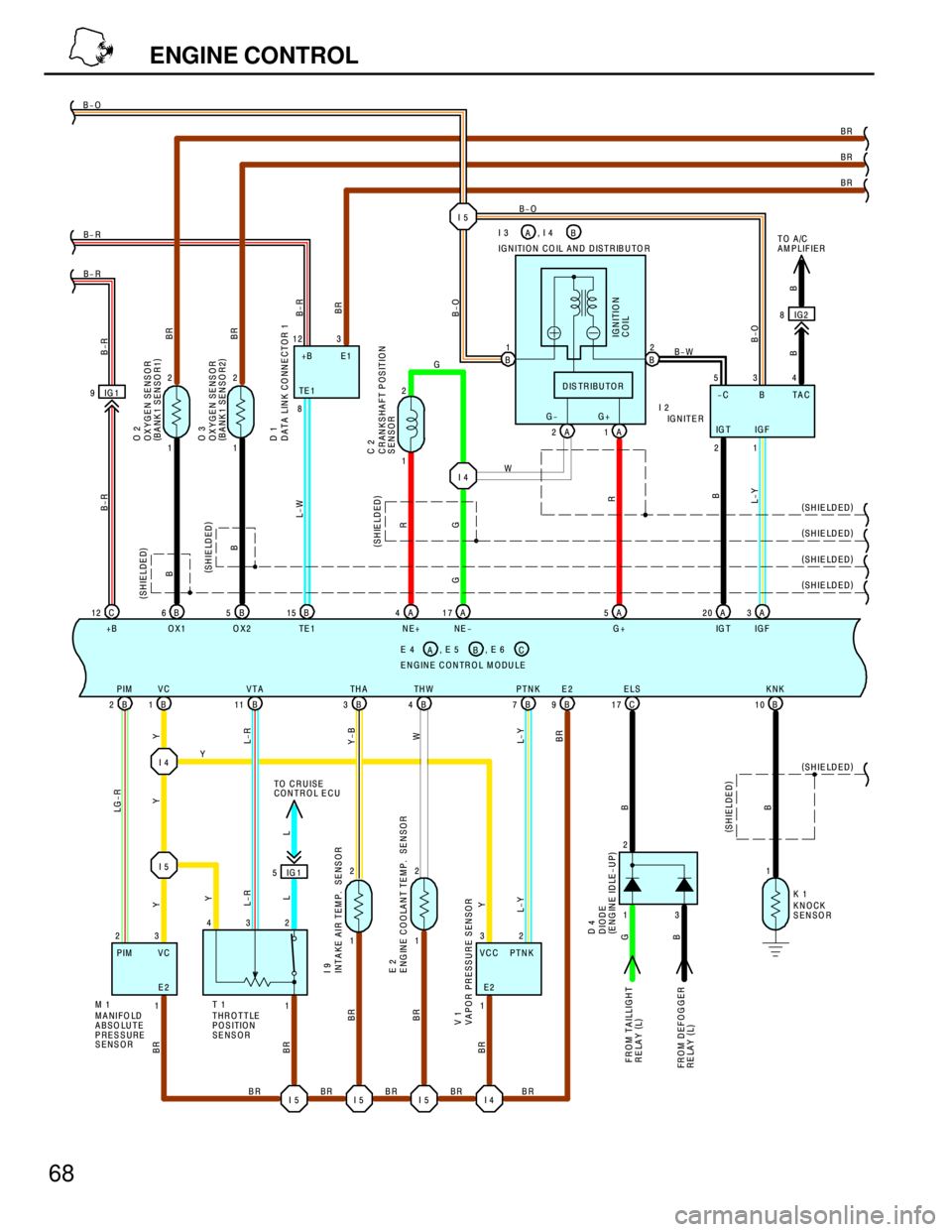
ENGINE CONTROL
I 4 IG 1 9
C 12
+BB 6
OX1B 5
OX2B 15
TE 1
B 2PIM
B 1VC
B 11VTA
B 3TH A
B 4TH W
B 7PTNK
B 9E2 B- R B- R B-O
BR
BR
Y
BR BR BR
B-R B-R
L-W B- R
BR LG-R
YY
L-R
Y-B
W
L- Y
BR BR
BR
B
B
BR
BR(
SHIELDED) (
SHIELDED)
A 5
G+ A 4
NE+A 17
NE -A 3
IG F
C 17ELS
B 10KNK
2
B B
(
SHIELDED)
(
SHIELDED)
MANIFOLD
ABSO LUTE
PRESSURE
SENSORTHROTTLE
POSITION
SENSOR
FROM TAI
RELAY (
L)
FR O M D EF
RELAY (
L)
CK
SO R ENGINE CONTROL MODULEB E 4 , E 5
AC, E 6
ENSOR
A 2 G-
A 1 G+ IGNITION COIL AND DISTRIBUTOR
I I 2 B1
B2
DISTRIBUTOR
B-O
BB-O
IG N ITIO N
COIL
A 20
IG T
R
G
R
B
L-Y (
SHIELDED)
BRB-O
1 2
1 2
OXYGEN SENSOR
(
BANK 1 SENSO R1)
OXYGEN SENSOR
(
BANK 1 SENSO R2) O 2
O 3
L
TO CRUISE
CONTROL ECU
V V
BR
B BBR
BR (
SHIELDED) (
SHIELDED)
I 5 I 5 I 5 I 4
DATA LINK CO NNECTOR 1 D 1
(
SHIELDED) (
SHIELDED)
B
TO A/C
AM PLIFIER
B-W
I 4W
G
I 5
B I 3 , I 4
A
IG2 8
1 2
CRANKSHAFT POSITION
SENSOR C 2
G
1 2
1 2
1 3 232
E2
Y
R
R
Y
L-Y
VCC PTNK1
G
BL-R
L Y
INTAKE AIR TEM P. SENSOR I 9
DIO
(
EN D 4
LLIG H T
OGGER
KNO
SEN K 1
ENGINE COOLANT TEMP. S E 2
IG 1 5
APOR PRESSURE SENSOR 1
I 5
8 12 3
TE 1+B E1
534
-C B TAC
IG T IG F
21 GNITER
3 1DE
GINE IDLE-UP)
1E2 VC PIM
M 11 432
T 1
Page 944 of 1354

K
1
234
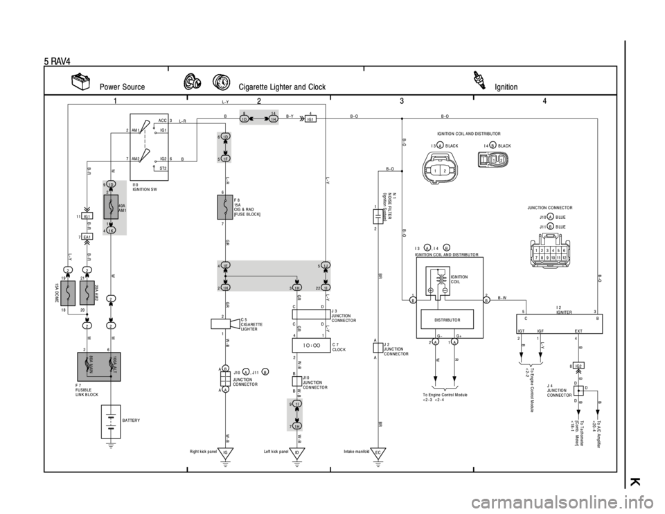
5 RAV4
1D 91D 6
1H 3 1F 5
40A
AM1
C 5
C IG ARETTE
LIG H TER 2
CLOC K C 7 1K 4
1E 4
1H 2
IG1H 71I 92 61
W-B
W-B GR L-Y
GR L- RW-B GRGR
Left kick panel
Power Source Cigarette Lighter and Clock Ignition
7ACC
IG1
IG2
ST2 AM 13
6 AM 2
6
F 8
15 A
CI G & R A D
[FUSE BLOCK]
2 2
214
1H
7EA1 11 IG1
228
1D
1J 5
1I 22
L-Y
IG14
2
217 L- RBB-YB-O
W
B-R B-R B-R
L-Y20A AM2 L-Y
I1 0
IG N ITIO N S W
W
W
1
F 7
FU SIBLE
LIN K B LO CK
BATTER Y
W
L-Y
4
2
80A MAIN100A ALT
G+B-W B-O
B- O B- O
BRBR B-O
14 2 1
3 5
1A 2A 1
B2
B
CB
IGT IGF EXT DISTRIBUTO R IG N ITIO N C O IL AN D DISTRIBU TO R
I 2
IG N ITE R I 3 AB-O
G-
2
N 1
N OISE FILTER
(
Ig nitio n S ystem)
IG N ITION
COIL
ECR L- Y
T o E ngine Control M odule
<2-2
To Engine Control M odule
<2-3 <2-4
Intak e ma nifo ld B
20
15A DO ME18 191 2
8IG2
D
DD
To T achometer
[C omb. M ete r]
<18-1
J 4
JU NC TIO N
CONNECTOR
B B BB
To A /C A mplifier
<20-4
B
B , I 4
W
A A
J 2
JUNCTION
CONNECTOR CD
CDJ 3
JUNCTION
CONNECTOR
ID AB
AA
W-B W-BB
BJ10
JUNCTION
CONNECTOR J10 A , J11 B
JU NC TIO N
CONNECTOR
Right kick panel12 A I 3 B LAC K BI 4 B LA C K IGNITION COIL AND DISTRIBUTOR
123456
7 8 9 101112B J11 B LUE J10 A B LUE JUNCTION CONNECTOR 12
Page 960 of 1354
IG0J3−02
− IGNITIONIGNITION SYSTEM
IG−1
1996 RAV4 (RM447U)
IGNITION SYSTEM
ON−VEHICLE INSPECTION
NOTICE:
”Cold” and ”Hot” in these sentences express the tempera-
ture of the coils themselves. ”Cold” is from −10°C (14°F) to
50°C (122°F) and ”Hot” is from 50°C (122°F) to 100°C
(212°F).
1. INSPECT IGNITERS AND SPARK TEST
Check that the spark occurs.
(1) Disconnect the high−tension cord (from the ignition
coil) from the distributor cap.
(2) Hold the end approx. 12.5 mm (0.50 in.) from the
body ground.
(3) See if spark occurs while engine is being cranked.
NOTICE:
To prevent gasoline from being injected from injectors dur-
ing this test, crank the engine for no more than 5 − 10 se-
conds at time.
If the spark does not occur, perform the test as follows:
Page 961 of 1354

SPARK TEST
CHECK CONNECTION OF IGNITION COIL, IGNITER
AND DISTRIBUTOR CONNECTORS.
CHECK RESISTANCE OF HIGH−TENSION CORDS
TRY ANOTHER IGNITER Maximum resistance: 25 kΩ per cord (See step 2)
CHECK POWER SUPPLY TO IGNITION COIL AND
IGNITER
1. Turn ignition switch to ON.
2. Check that there is battery positive voltage at ignition coil
positive (+) terminal.
Check wiring between ECM, distributor
and igniter, and then try another ECM.
CHECK IGT SIGNAL FROM ECM
NO
BAD
OK
OK
OK
Connect securely.
Replace the cord(s).
Check wiring between ignition switch
to ignition coil and igniter.
BAD
BAD
BAD
(See page DI−100)
Cold Hot
0.36 − 0.55 Ω0.45 − 0.65 Ω CHECK RESISTANCE OF IGNITION COILOKReplace the ignition coil.
BAD Resistance: (See step 4)
Primary
Secondary
9.0 − 15.4 kΩ11.4 − 18.1 kΩ
CHECK RESISTANCE OF SIGNAL GENERATOR
Resistance: Cold HotOKReplace the distributor housing assembly.(PICKUP COIL)
(See step 5)
135 − 220 Ω175 − 255 Ω
CHECK RESISTANCE OF CRANKSHAFT POSITION
SENSOR
Resistance: Cold HotOK
Replace the crankshaft position sensor.
(See step 6)
985 − 1,600 Ω1,265 − 1,890 ΩBAD
BAD
OK
CHECK AIR GAP OF DISTRIBUTOR
Air gap: 0.2 − 0.4 mm (0.008 − 0.016 in.)Replace the distributor housing assembly.(See step 5)
BAD IG−2
− IGNITIONIGNITION SYSTEM
1996 RAV4 (RM447U)