Page 1134 of 1354
SA1YB−02
FA1535
SST
R10849
SA−20
− SUSPENSION AND AXLEFRONT DRIVE SHAFT
1996 RAV4 (RM447U)
REMOVAL
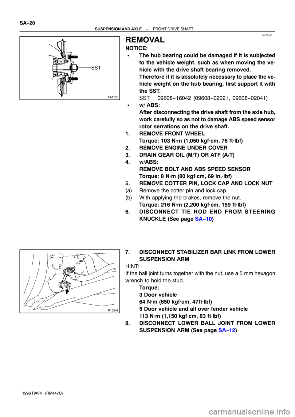
NOTICE:
�The hub bearing could be damaged if it is subjected
to the vehicle weight, such as when moving the ve-
hicle with the drive shaft bearing removed.
Therefore if it is absolutely necessary to place the ve-
hicle weight on the hub bearing, first support it with
the SST.
SST 09608−16042 (09608−02021, 09608−02041)
�w/ ABS:
After disconnecting the drive shaft from the axle hub,
work carefully so as not to damage ABS speed sensor
rotor serrations on the drive shaft.
1. REMOVE FRONT WHEEL
Torque: 103 N·m (1,050 kgf·cm, 76 ft·lbf)
2. REMOVE ENGINE UNDER COVER
3. DRAIN GEAR OIL (M/T) OR ATF (A/T)
4. w/ABS:
REMOVE BOLT AND ABS SPEED SENSOR
Torque: 8 N·m (80 kgf·cm, 69 in.·lbf)
5. REMOVE COTTER PIN, LOCK CAP AND LOCK NUT
(a) Remove the cotter pin and lock cap.
(b) With applying the brakes, remove the nut.
Torque: 216 N·m (2,200 kgf·cm, 159 ft·lbf)
6. D I S C O N N E C T T I E R O D E N D F R O M S T E E R I N G
KNUCKLE (See page SA−10)
7. DISCONNECT STABILIZER BAR LINK FROM LOWER
SUSPENSION ARM
HINT:
If the ball joint turns together with the nut, use a 5 mm hexagon
wrench to hold the stud.
Torque:
3 Door vehicle
64 N·m (650 kgf·cm, 47ft·lbf)
5 Door vehicle and all over fender vehicle
113 N·m (1,150 kgf·cm, 83 ft·lbf)
8. DISCONNECT LOWER BALL JOINT FROM LOWER
SUSPENSION ARM (See page SA−12)
Page 1147 of 1354
SA0TL−03
R10850
R10823
− SUSPENSION AND AXLEFRONT SHOCK ABSORBER
SA−33
1996 RAV4 (RM447U)
REMOVAL
1. REMOVE FRONT WHEEL
Torque: 103 N·m (1,050 kgf·cm, 76 ft·lbf)
2. DISCONNECT FLEXIBLE HOSE AND ABS SPEED
SENSOR WIRE HARNESS (w/ ABS) FROM SHOCK
ABSORBER
Remove the 2 bolts and disconnect the flexible hose and ABS
speed sensor wire harness.
Torque:
Flexible hose: 19 N·m (192 kgf·cm, 14 ft·lbf)
ABS wire harness: 5 N·m (55 kgf·cm, 48 in.·lbf)
3. DISCONNECT SHOCK ABSORBER FROM STEERING
KNUCKLE
Torque: 158 N·m (1,610 kgf·cm, 117 ft·lbf)
HINT:
At the time of installation, please refer to the following item.
Coat the nut’s threads with engine oil.
4. REMOVE SHOCK ABSORBER WITH COIL SPRING
Remove the 3 nuts, suspension support No.2 and shock ab-
sorber with the coil spring.
Torque: 80 N·m (820 kgf·cm, 59 ft·lbf)
Page 1154 of 1354
SA0TS−03
R10828
A
A B
R10829
W01708
SA−40
− SUSPENSION AND AXLEFRONT LOWER SUSPENSION ARM
1996 RAV4 (RM447U)
REMOVAL
1. REMOVE FRONT WHEEL
Torque: 103 N·m (1,050 kgf·cm, 76 ft·lbf)
2. A/T LH:
REMOVE LH ENGINE UNDER COVER
3. EXCEPT A/T LH:
DISCONNECT STABILIZER BAR LINK FROM LOWER
SUSPENSION ARM (See page SA−48)
4. A/T LH:
REMOVE STABILIZER BAR (See page SA−48)
5. DISCONNECT LOWER SUSPENSION ARM FROM
LOWER BALL JOINT
Remove the bolt and 2 nuts.
Torque: 127 N·m (1,300 kgf·cm, 94 ft·lbf)
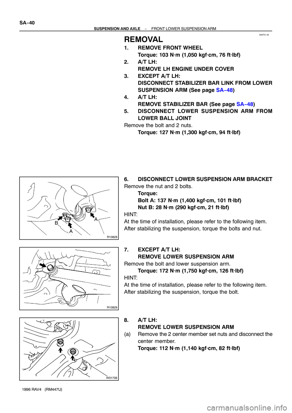
6. DISCONNECT LOWER SUSPENSION ARM BRACKET
Remove the nut and 2 bolts.
Torque:
Bolt A: 137 N·m (1,400 kgf·cm, 101 ft·lbf)
Nut B: 28 N·m (290 kgf·cm, 21 ft·lbf)
HINT:
At the time of installation, please refer to the following item.
After stabilizing the suspension, torque the bolts and nut.
7. EXCEPT A/T LH:
REMOVE LOWER SUSPENSION ARM
Remove the bolt and lower suspension arm.
Torque: 172 N·m (1,750 kgf·cm, 126 ft·lbf)
HINT:
At the time of installation, please refer to the following item.
After stabilizing the suspension, torque the bolt.
8. A/T LH:
REMOVE LOWER SUSPENSION ARM
(a) Remove the 2 center member set nuts and disconnect the
center member.
Torque: 112 N·m (1,140 kgf·cm, 82 ft·lbf)
Page 1233 of 1354
SF0QI−03
S01903
S01939
(1)
(2)
S01827
S01949
Disconnect
Spacer
− SFIINJECTOR
SF−19
1996 RAV4 (RM447U)
REMOVAL
1. REMOVE AIR CLEANER ASSEMBLY (See page
ST−4)
2. REMOVE CYLINDER HEAD COVER (See page
EM−33)
3. DISCONNECT THROTTLE BODY FROM INTAKE MAN-
IFOLD (See page SF−30)
4. REMOVE DISTORIBUTOR (See page IG−9)
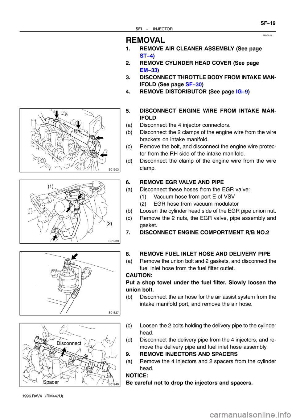
5. DISCONNECT ENGINE WIRE FROM INTAKE MAN-
IFOLD
(a) Disconnect the 4 injector connectors.
(b) Disconnect the 2 clamps of the engine wire from the wire
brackets on intake manifold.
(c) Remove the bolt, and disconnect the engine wire protec-
tor from the RH side of the intake manifold.
(d) Disconnect the clamp of the engine wire from the wire
clamp.
6. REMOVE EGR VALVE AND PIPE
(a) Disconnect these hoses from the EGR valve:
(1) Vacuum hose from port E of VSV
(2) EGR hose from vacuum modulator
(b) Loosen the cylinder head side of the EGR pipe union nut.
(c) Remove the 2 nuts, the EGR valve, pipe assembly and
gasket.
7. DISCONNECT ENGINE COMPORTMENT R/B NO.2
8. REMOVE FUEL INLET HOSE AND DELIVERY PIPE
(a) Remove the union bolt and 2 gaskets, and disconnect the
fuel inlet hose from the fuel filter outlet.
CAUTION:
Put a shop towel under the fuel filter. Slowly loosen the
union bolt.
(b) Disconnect the air hose for the air assist system from the
intake manifold port, and remove the air hose.
(c) Loosen the 2 bolts holding the delivery pipe to the cylinder
head.
(d) Disconnect the delivery pipe from the 4 injectors, and re-
move the delivery pipe and fuel inlet hose assembly.
9. REMOVE INJECTORS AND SPACERS
(a) Remove the 4 injectors and 2 spacers from the cylinder
head.
NOTICE:
Be careful not to drop the injectors and spacers.
Page 1244 of 1354
SF0QQ−03
S01905
(4) (3)
(2)
(1)
S01907
A
B
Protrusion
(Bolt: Type A)
(Nut: Type B)B A
S01902
(1)
(3)(2) SF−30
− SFITHROTTLE BODY
1996 RAV4 (RM447U)
REMOVAL
1. DRAIN ENGINE COOLANT
2. A/T:
DISCONNECT THROTTLE CABLE FROM THROTTLE
BODY
3. DISCONNECT ACCELERATOR CABLE FROM
THROTTLE BODY
4. REMOVE AIR CLEANER CAP ASSEMBLY (See page
ST−4)
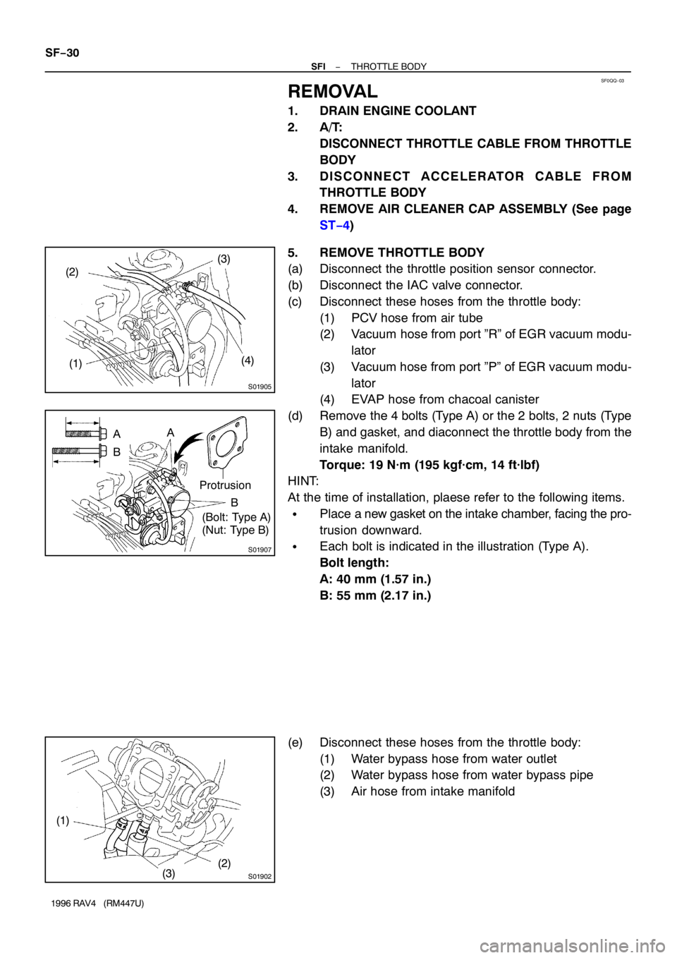
5. REMOVE THROTTLE BODY
(a) Disconnect the throttle position sensor connector.
(b) Disconnect the IAC valve connector.
(c) Disconnect these hoses from the throttle body:
(1) PCV hose from air tube
(2) Vacuum hose from port ”R” of EGR vacuum modu-
lator
(3) Vacuum hose from port ”P” of EGR vacuum modu-
lator
(4) EVAP hose from chacoal canister
(d) Remove the 4 bolts (Type A) or the 2 bolts, 2 nuts (Type
B) and gasket, and diaconnect the throttle body from the
intake manifold.
Torque: 19 N·m (195 kgf·cm, 14 ft·lbf)
HINT:
At the time of installation, plaese refer to the following items.
�Place a new gasket on the intake chamber, facing the pro-
trusion downward.
�Each bolt is indicated in the illustration (Type A).
Bolt length:
A: 40 mm (1.57 in.)
B: 55 mm (2.17 in.)
(e) Disconnect these hoses from the throttle body:
(1) Water bypass hose from water outlet
(2) Water bypass hose from water bypass pipe
(3) Air hose from intake manifold
Page 1268 of 1354
SF0RG−02
S01838
2WD
SST
P01630
Ohmmeter
− SFIKNOCK SENSOR
SF−57
1996 RAV4 (RM447U)
INSPECTION
1. 4WD:
REMOVE ENGINE AND TRANSAXLE ASSEMBLY (See
page EM−68)
2. REMOVE KNOCK SENSOR
(a) Disconnect the knock sensor connector.
(b) Using SST, remove the knock sensor.
SST 09816−30010
Torque: 44 N·m (450 kgf·cm, 33 ft·lbf)
3. INSPECT KNOCK SENSOR
Using an ohmmeter, check that there is no continuity between
the terminal and body.
If there is continuity, replace the sensor.
4. REINSTALL KNOCK SENSOR
Installation is in the reverse order of removal.
5. 4WD:
REINSTALL ENGINE AND TRANSAXLE ASSEMBLY
(See page EM−74)
Page 1307 of 1354
SR0FW−02
R10965
Z13365
Pressure
Feed Tube
SST
R10984
R10966
− STEERINGPOWER STEERING VANE PUMP
SR−33
1996 RAV4 (RM447U)
REMOVAL
1. REMOVE RH AND LH ENGINE UNDER COVERS
Remove the 13 bolts.
2. REMOVE FRONT EXHAUST PIPE
Remove the 2 bolts, 3 nuts and 2 gaskets.
3. REMOVE STABILIZER BAR WITH LINK
(See page SA−48)
4. DISCONNECT RH AND LH LOWER SUSPENSION
ARMS (See page SA−40)
5. REMOVE 2 PS GEAR ASSEMBLY SET BOLTS AND
NUTS
6. REMOVE FRONT SUSPENSION CROSSMEMBER AS-
SEMBLY (See page SA−40)
7. DISCONNECT 2 TUBE CLAMPS
Remove the bolt.
8. DISCONNECT 2 VACUUM HOSES
9. DISCONNECT RETURN HOSE
NOTICE:
Take care not to spill fluid on the drive belt.
10. REMOVE DRIVE BELT
Loosen the 2 bolts.
11. DISCONNECT PRESSURE FEED TUBE
Using SST, disconnect the tube.
SST 09631−22020
12. REMOVE PS VANE PUMP ASSEMBLY WITH PUMP
BRACKET
Remove the 3 bolts.
13. REMOVE PRESSURE FEED TUBE
Remove the union bolt, gasket and tube from the PS vane
pump assembly.
Page 1321 of 1354
SR0G2−03
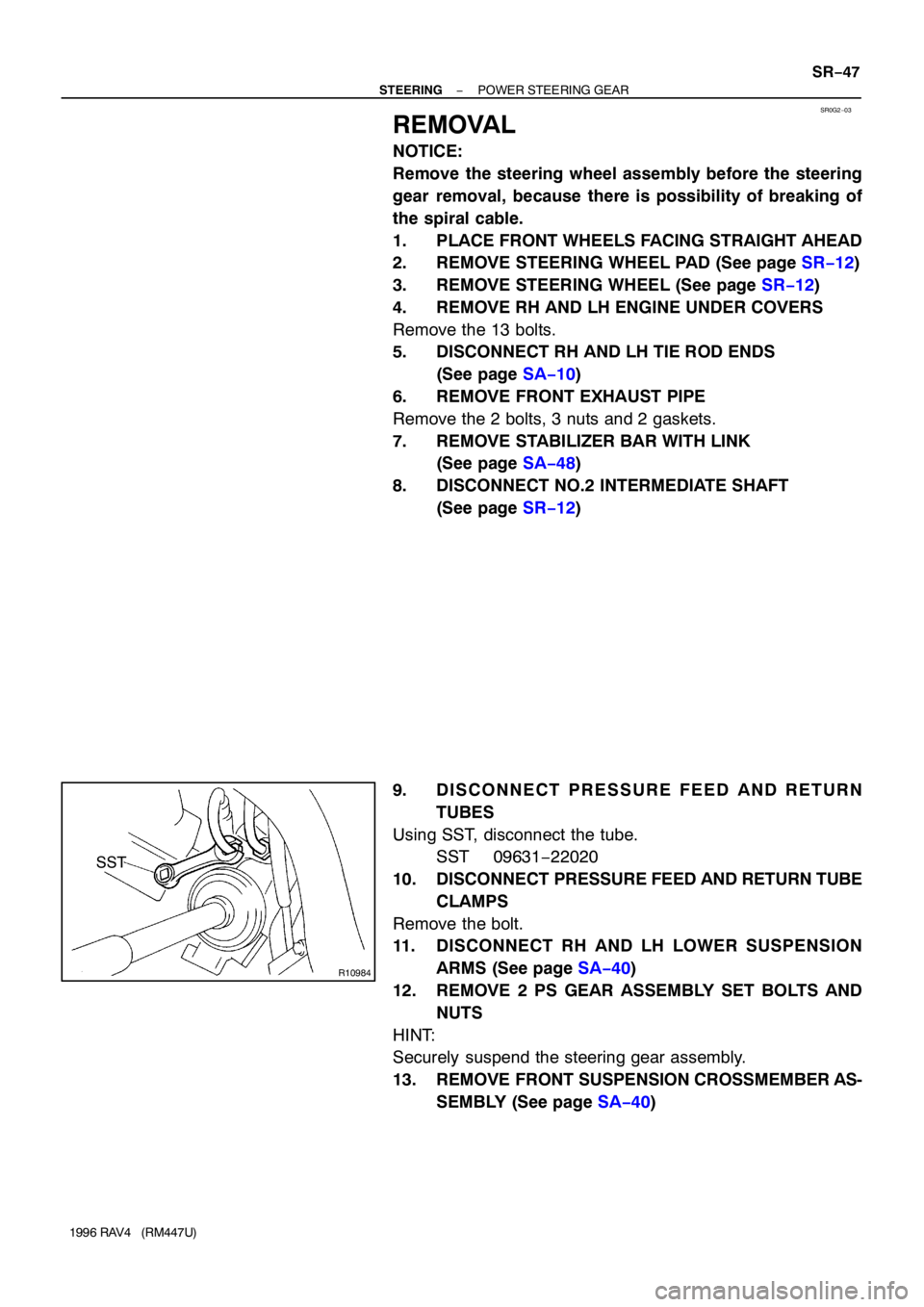
R10984
SST
− STEERINGPOWER STEERING GEAR
SR−47
1996 RAV4 (RM447U)
REMOVAL
NOTICE:
Remove the steering wheel assembly before the steering
gear removal, because there is possibility of breaking of
the spiral cable.
1. PLACE FRONT WHEELS FACING STRAIGHT AHEAD
2. REMOVE STEERING WHEEL PAD (See page SR−12)
3. REMOVE STEERING WHEEL (See page SR−12)
4. REMOVE RH AND LH ENGINE UNDER COVERS
Remove the 13 bolts.
5. DISCONNECT RH AND LH TIE ROD ENDS
(See page SA−10)
6. REMOVE FRONT EXHAUST PIPE
Remove the 2 bolts, 3 nuts and 2 gaskets.
7. REMOVE STABILIZER BAR WITH LINK
(See page SA−48)
8. DISCONNECT NO.2 INTERMEDIATE SHAFT
(See page SR−12)
9. DISCONNECT PRESSURE FEED AND RETURN
TUBES
Using SST, disconnect the tube.
SST 09631−22020
10. DISCONNECT PRESSURE FEED AND RETURN TUBE
CLAMPS
Remove the bolt.
11. DISCONNECT RH AND LH LOWER SUSPENSION
ARMS (See page SA−40)
12. REMOVE 2 PS GEAR ASSEMBLY SET BOLTS AND
NUTS
HINT:
Securely suspend the steering gear assembly.
13. REMOVE FRONT SUSPENSION CROSSMEMBER AS-
SEMBLY (See page SA−40)