Page 215 of 1354

GENERAL REPAIR INSTRUCTIONS
Work Precautions
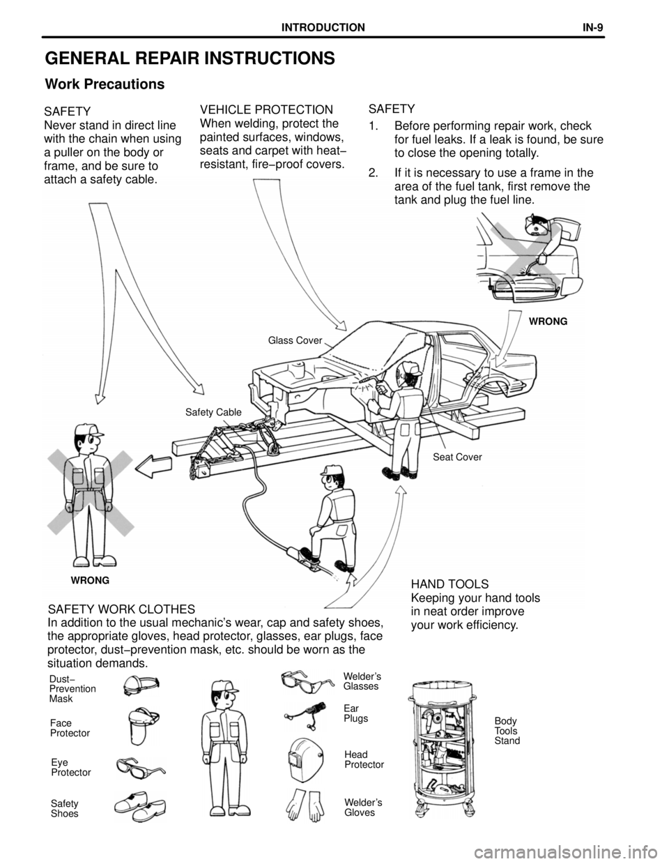
VEHICLE PROTECTION
When welding, protect the
painted surfaces, windows,
seats and carpet with heat-
resistant, fire-proof covers. SAFETY
Never stand in direct line
with the chain when using
a puller on the body or
frame, and be sure to
attach a safety cable.SAFETY
1. Before performing repair work, check
for fuel leaks. If a leak is found, be sure
to close the opening totally.
2. If it is necessary to use a frame in the
area of the fuel tank, first remove the
tank and plug the fuel line.
WRONG
Glass Cover
Safety Cable
Seat Cover
WRONG
HAND TOOLS
Keeping your hand tools
in neat order improve
your work efficiency. SAFETY WORK CLOTHES
In addition to the usual mechanic's wear, cap and safety shoes,
the appropriate gloves, head protector, glasses, ear plugs, face
protector, dust-prevention mask, etc. should be worn as the
situation demands.
Dust-
Prevention
MaskWelder's
Glasses
Ear
Plugs
Face
ProtectorBody
Tools
Stand
Head
Protector Eye
Protector
Welder's
Gloves Safety
Shoes
INTRODUCTIONINœ9
Page 335 of 1354

− DIAGNOSTICSENGINE
DI−15
1996 RAV4 (RM447U) DTC No.
(See Page)
Detection ItemTrouble AreaMILMemory
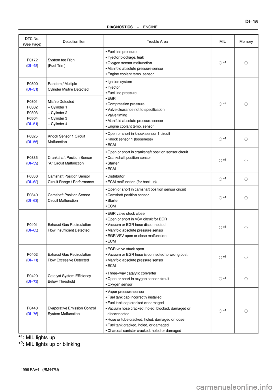
P0172
(DI−48)System too Rich
(Fuel Trim)
�Fuel line pressure
�Injector blockage, leak
�Oxygen sensor malfunction
�Manifold absolute pressure sensor
�Engine coolant temp. sensor
� *1�
P0300
(DI−51)Random / Multiple
Cylinder Misfire Detected�Ignition system
�Injector
�Fuel line pressure
�EGR
�Compression pressure
�Valve clearance not to specification
�Valve timing
�Manifold absolute pressure sensor
�Engine coolant temp. sensor
� *2�P0301
P0302
P0303
P0304
(DI−51)Misfire Detected
− Cylinder 1
− Cylinder 2
− Cylinder 3
− Cylinder 4
P0325
(DI−56)Knock Sensor 1 Circuit
Malfunction�Open or short in knock sensor 1 circuit
�Knock sensor 1 (looseness)
�ECM
� *1�
P0335
(DI−59)Crankshaft Position Sensor
”A” Circuit Malfunction
�Open or short in crankshaft position sensor circuit
�Crankshaft position sensor
�Starter
�ECM
� *1�
P0336
(DI−62)Camshaft Position Sensor
Circuit Range / Performance�Distributor
�ECM malfunction (for back up)� *1�
P0340
(DI−63)Camshaft Position Sensor
Circuit Malfunction
�Open or short in camshaft position sensor circuit
�Camshaft position sensor
�Starter
�ECM
� *1�
P0401
(DI−65)Exhaust Gas Recirculation
Flow Insufficient Detected
�EGR valve stuck close
�Open or short in VSV circuit for EGR
�Vacuum or EGR hose disconnected
�Manifold absolute pressure sensor
�EGR VSV open or close malfunction
�ECM
� *1�
P0402
(DI−71)Exhaust Gas Recirculation
Flow Excessive Detected
�EGR valve stuck open
�Vacuum or EGR hose is connected to wrong post
�Manifold absolute pressure sensor
�ECM
� *1�
P0420
(DI−73)Catalyst System Efficiency
Below Threshold�Three−way catalytic converter
�Open or short in oxygen sensor circuit
�Oxygen sensor
� *1�
P0440
(DI−76)Evaporative Emission Control
System Malfunction
�Vapor pressure sensor
�Fuel tank cap incorrectly installed
�Fuel tank cap cracked or damaged
�Vacuum hose cracked, holed, blocked, damaged or
disconnected
�Hose or tube cracked, holed, damaged or loose
�Fuel tank cracked, holed, or damaged
�Charcoal canister cracked, holed or damaged
� *1�
*1: MIL lights up
*
2: MIL lights up or blinking
Page 345 of 1354

FI4741
20 30
10
5
3
2
0.1 0.2 0.3 0.51
−20
(−4) 0
(32) 20
(68) 40
(104) 60
(140) 80
(176)100
(212)
Temperature °C (°F) Acceptable
Resistance (Ω)
(fig. 1)
− DIAGNOSTICSENGINE
DI−25
1996 RAV4 (RM447U)
DTC P0110 Intake Air Temp. Circuit Malfunction
CIRCUIT DESCRIPTION
The intake air temp. sensor is built into the air cleaner cap and
senses the intake air temperature.
A thermistor built in the sensor changes the resistance value
according to the intake air temperature.
The lower the intake air temperature, the greater the thermistor
resistance value, and the higher the intake air temperature, the
lower the thermistor resistance value (See Fig. 1.).
The intake air temperature sensor is connected to the ECM
(See next page). The 5 V power source voltage in the ECM is
applied to the intake air temperature sensor from the terminal
THA via a resistor R.
That is , the resistor R and the intake air temperature sensor are
connected in series. When the resistance value of the intake air
temperature sensor changes in accordance with changes in the
intake air temperature, the potential at terminal THA also
changes. Based on this signal, the ECM increases the fuel in-
jection volume to improve driveability during cold engine opera-
tion.
If the ECM detects the DTC ”P0110”, it operates the fail safe
function in which the intake air temperature is assumed to be
20°C (68°F).
Intake Air Temp.
°C (°F)Resistance
(kΩ)Voltage
(V)
−20 (−4)16.24.3
0 (32)5.93.4
20 (68)2.52.4
40 (104)1.11.4
60 (140)0.60.9
80 (176)0.30.5
100 (212)0.20.3
DTC No.DTC Detecting ConditionTrouble Area
P0110Open or short in intake air temp. sensor circuit
�Open or short in intake air temp. sensor circuit
�Intake air temp. sensor
�ECM
HINT:
After confirming DTC P0110 use the OBDII scan tool or TOYOTA hand−held tester to confirm the intake air
temperature from ”CURRENT DATA”.
Temperature DisplayedMalfunction
− 40°C (− 40°F)Open circuit
140°C (284°F) or moreShort circuit
DI3ZE−01
Page 396 of 1354

(2) (1)
(5)
S00043
ECM
VSV
for EVAP
Fuel Tank
Charcoal CanisterVSV for Vapor
Pressure SensorVapor Pressure
Sensor
(4)
(3) DI−76
− DIAGNOSTICSENGINE
1996 RAV4 (RM447U)
DTC P0440 Evaporative Emission Control System
Malfunction
CIRCUIT DESCRIPTION
The vapor pressure sensor and VSV for vapor pressure sensor are used to detect abnormalities in the evap-
orative emission control system.
The ECM decides whether there is an abnormality in the evaporative emission control system based on the
vapor pressure sensor signal.
DTC P0440 is recorded by the ECM when evaporative emissions leak from the components within the dotted
line in fig. 1 below, or when the vapor pressure sensor malfunctions.
DTC No.DTC Detecting ConditionTrouble Area
P0440
The fuel tank pressure is atmospheric pressure after the ve-
hicle is driven for 20 min.
(2 trip detection logic)
�Vapor pressure sensor
�Fuel tank cap incorrectly installed
�Fuel tank cap cracked or damaged
�Vacuum hose cracked, holed, blocked, damaged or discon-
nected ( (1) or (2) in fig. 1 ) ( (3) in fig. 1 )
�Fuel tank cranked, holed or damaged
�Charcoal canister cracked, holed or damaged
DI3ZW−01
Page 397 of 1354
S02388
6
66
6 3
15
2
1J 1E21J/B No.1 From
BatteryVaper Pressure Sensor
E5
E5
E5
E4
E58 229
7 1
EA1
B−R
B−O
11Fuse Block
From
IG SwitchVSV
(for Vapor
Pressure Sensor) VSV
(for EVAP)VC
PTNK
E2
EVP
TPCE01
E01 5V ECM
E1
B−R
1P
2 1
B−R BRL−Y Y
1 2 3
R/B No.6
2
B−R
W−B2
EA 10
IGN R−W
EFI Main Relay
R−W A
A
W−B
J1 Junction
Connector B−O
− DIAGNOSTICSENGINE
DI−77
1996 RAV4 (RM447U)
WIRING DIAGRAM
INSPECTION PROCEDURE
HINT:
�If DTC P0441, P0446 or P0450 is output after DTC P0440, first troubleshoot DTC P0441, P0446 or
P0450. If no malfunction is detected, troubleshoot DTC P0440 next.
�Ask the customer whether, after the MIL came on, the customer found the fuel tank cap loose and tight-
ened it. Also ask the customer whether the fuel tank cap was loose when refuelling.
If the fuel tank cap was loose, it was the cause of the DTC. If the fuel tank cap was not loose or if the
customer was not sure if it was loose, troubleshoot according to the following procedure.
Page 398 of 1354
S00046
DI−78
− DIAGNOSTICSENGINE
1996 RAV4 (RM447U)
1 Check whether the hoses close to the fuel tank have been modified, and check
whether there are signs of any accident near the fuel tank or charcoal canister.
CHECK:
Check for cracks, deformation and loose connection of the fol-
lowing parts.
�Fuel tank
�Charcoal canister
�Fuel tank filler pipe
�Hoses and tubes around the fuel tank and charcoal
canister
NG Repair or replace.
OK
2 Check that the fuel tank cap is TOYOTA genuine parts.
NG Replace to TOYOTA genuine parts.
OK
3 Check that the fuel tank cap is correctly installed.
NG Correctly install the fuel tank cap.
OK
4 Check the fuel tank cap (See page EC−5).
NG Replace fuel tank cap.
OK
Page 399 of 1354

− DIAGNOSTICSENGINE
DI−79
1996 RAV4 (RM447U)
5 Check the filler neck for damage.
PREPARATION:
Remove the fuel tank cap.
CHECK:
Visually inspect the filler neck for damage.
NG Replace the filler neck.
OK
6 Check the vacuum hoses between vapor pressure sensor and VSV for vapor
pressure sensor, and VSV for vapor pressure sensor and charcoal canister.
CHECK:
(a) Check that the vacuum hose is connected correctly.
(b) Check the vacuum hose for looseness and disconnection.
(c) Check the vacuum hose for cracks, hole and damage.
NG Repair or replace.
OK
7 Check the hose and tube between fuel tank and charcoal canister.
CHECK:
(a) Check for proper connection of the fuel tank and fuel evap pipe (See page SF−1), fuel evap pipe and
fuel tube under the floor, fuel tube under the floor and charcoal canister.
(b) Check the hose and tube for cracks, hole and damage.
NG Repair or replace.
OK
8 Check the charcoal canister for cracks, hole and damage (See page EC−5).
NG Replace charcoal canister.
OK
Page 401 of 1354
S00048
Pressure
− DIAGNOSTICSENGINE
DI−81
1996 RAV4 (RM447U)
NG Repair or replace harness or connector.
OK
Replace vapor pressure senor.
12 Check the fuel tank for cracks and damage.
PREPARATION:
(a) Disconnect the vacuum hose from charcoal canister.
(b) Correctly install the fuel tank cap.
(c) Apply a pressure of 5 kPa (0.05 kgf/cm
2, 0.71 psi) to the
fuel tank.
CHECK:
Check whether the pressure is maintained after 1 minute.
OK:
Pressure applied to the fuel tank is maintained.
NG Replace fuel tank.
OK
It is likely that the vehicle user did not properly close the fuel tank cap. Please explain to the cus-
tomer how to properly install the fuel tank cap.