Page 221 of 1354
ABS Antilock Brake System
A/C Air Conditioner
assy assembly
ECT Electronic Controlled Transmission
ECU Electronic Control Unit
e.g. Exempli Gratia (for Example)
Ex. Except
FWD Front Wheel Drive Vehicles
4WD Four Wheel Drive Vehicles
in. inch
LH Left-hand
LHD Left-hand Drive
MIG Metal Inert Gas
M/Y Model Year
PPS Progressive Power Steering
RH Right-hand
RHD Right-hand Drive
SRS Supplemental Restraint System
w/ with
w/o without
ABBREVIATIONS USED IN THIS MANUAL
For convenience, the following abbreviations are used in this
manual.
INTRODUCTIONINœ15
Page 325 of 1354
 Terminal No.
Connection / Voltage or ResistanceCondition
2Bus � Line / Pulse generationDuring transmission
4Chassis Ground / ↔ Body Ground 1")
S02459
− DIAGNOSTICSENGINE
DI−5
1996 RAV4 (RM447U) Terminal No.
Connection / Voltage or ResistanceCondition
2Bus � Line / Pulse generationDuring transmission
4Chassis Ground / ↔ Body Ground 1 Ω or lessAlways
5Signal Ground / ↔ Body Ground 1 Ω or lessAlways
16Battery Positive / ↔ Body Ground 9 ∼ 14VAlways
HINT:
If your display shows ”UNABLE TO CONNECT TO VEHICLE”
when you have connected the cable of the OBDII scan tool or
TOYOTA hand−held tester to DLC3, turned the ignition switch
ON and operated the scan tool, there is a problem on the ve-
hicle side or tool side.
�If communication is normal when the tool is connected to
another vehicle, inspect DLC3 on the original vehicle.
�If communication is still not possible when the tool is con-
nected to another vehicle, the problem is probably in the
tool itself, so consult the Service Department listed in the
tool’s instruction manual.
2. INSPECT DIAGNOSIS (Normal Mode)
(a) Check the MIL.
(1) The MIL comes on when the ignition switch is turned
ON and the engine is not running.
HINT:
If the MIL does not light up, troubleshoot the combination meter.
(2) When the engine is started, the MIL should go off.
If the lamp remains on,the diagnosis system has
detected a malfunction or abnormality in the sys-
tem.
(b) Check the DTC.
NOTICE:
TOYOTA hand−held tester only:
When the diagnosis system is switched from normal mode
to check mode, it erases all DTC and freezed frame data re-
corded in normal mode. So before switching modes, al-
ways check the DTC and freezed frame data, and note them
down.
(1) Prepare the OBDII scan tool (complying with SAE
J1978) or TOYOTA hand−held tester.
(2) Connect the OBDII scan tool or TOYOTA hand−
held tester to DLC3 at the lower of the instrument
panel.
(3) Turn the ignition switch ON and turn the OBDII scan
tool or TOYOTA hand−held tester switch ON.
(4) Use the OBDII scan tool or TOYOTA hand−held tes-
ter to check the DTC and freezed frame data, note
them down.
(5) See page DI−14 to confirm the details of the
DTC.
Page 502 of 1354
D00697
Ok if hot
Add if hot
AT4252
0 − 1 mm
D02248
DI−182
− DIAGNOSTICSAUTOMATIC TRANSAXLE (A540H)
1996 RAV4 (RM447U)
(f) Check the fluid leaks.
Check for leaks in the transmission and transfer.
If there are leaks, it is necessary to repair or replace O − rings,
FIPG’s, oil seals or other parts.
(g) Inspect and adjust the throttle cable.
(1) Check that the throttle valve is fully closed.
(2) Check that the inner cable is not slack.
(3) Loosen the adjustment nuts.
(4) Adjust the outer cable so that the distance between
the end of the boot and stopper on the cable is as
standard.
Standard boot and cable stopper distance:
0 − 1 mm (0 − 0.04 in.)
(5) Tighten the adjusting nuts.
(6) Recheck the adjustments.
(h) Adjust the shift control cable.
(1) Loosen the nut on the lever.
(2) Push the manual lever fully toward the right side of
the vehicle.
Page 677 of 1354

IGNITION TIMING
INSPECTION
1. WARM UP ENGINE
Allow the engine")
EM0EJ−01
S01354
TOYOTA
Hand−held Tester
S01261
DLC1
TE1
E1SST
S01272
− ENGINE MECHANICALIGNITION TIMING
EM−11
1996 RAV4 (RM447U)
IGNITION TIMING
INSPECTION
1. WARM UP ENGINE
Allow the engine to warm up to normal operating temperature.
2. CONNECT TOYOTA HAND−HELD TESTER OR OBD II
SCAN TOOL
(a) Remove the fuse cover on the instrument panel.
(b) Connect the TOYOTA hand−held tester or OBD II scan
tool to the DLC3.
(c) Please refer to the TOYOTA hand−held tester or OBD II
scan tool operator’s manual for further details.
3. CONNECT TIMING LIGHT TO ENGINE
4. INSPECT IGNITION TIMING
(a) Using SST, connect terminals TE1 and E1 of the DLC1.
SST 09843−18020
(b) Using a timing light, check the ignition timing.
Ignition timing:
8 − 12° BTDC @ idle
(Transmission in neutral position)
(c) Remove the SST from the DLC1.
SST 09843−18020
5. FURTHER CHECK IGNITION TIMING
Ignition timing:
0 − 10° BTDC @ idle
(Transmission in neutral position)
HINT:
The timing mark moves in a range between 0° and 10°
6. DISCONNECT TIMING LIGHT FROM ENGINE
7. DISCONNECT TOYOTA HAND−HELD TESTER OR
OBD II SCAN TOOL
Page 1005 of 1354
Q06187
Q06188
Q06189
MX−10
− MANUAL TRANSAXLEMANUAL TRANSAXLE UNIT (4WD)
1996 RAV4 (RM447U)
(b) Pull straight until there is a gap of about 60−80 mm
(2.4−3.1 in.) between the engine and transaxle case.
(c) Move the transmission case cover in the direction, as
shown in the illustration.
(d) While holding transfer output, gently pull out whole trans-
axle.
Page 1007 of 1354
MX05U−01
Q09032
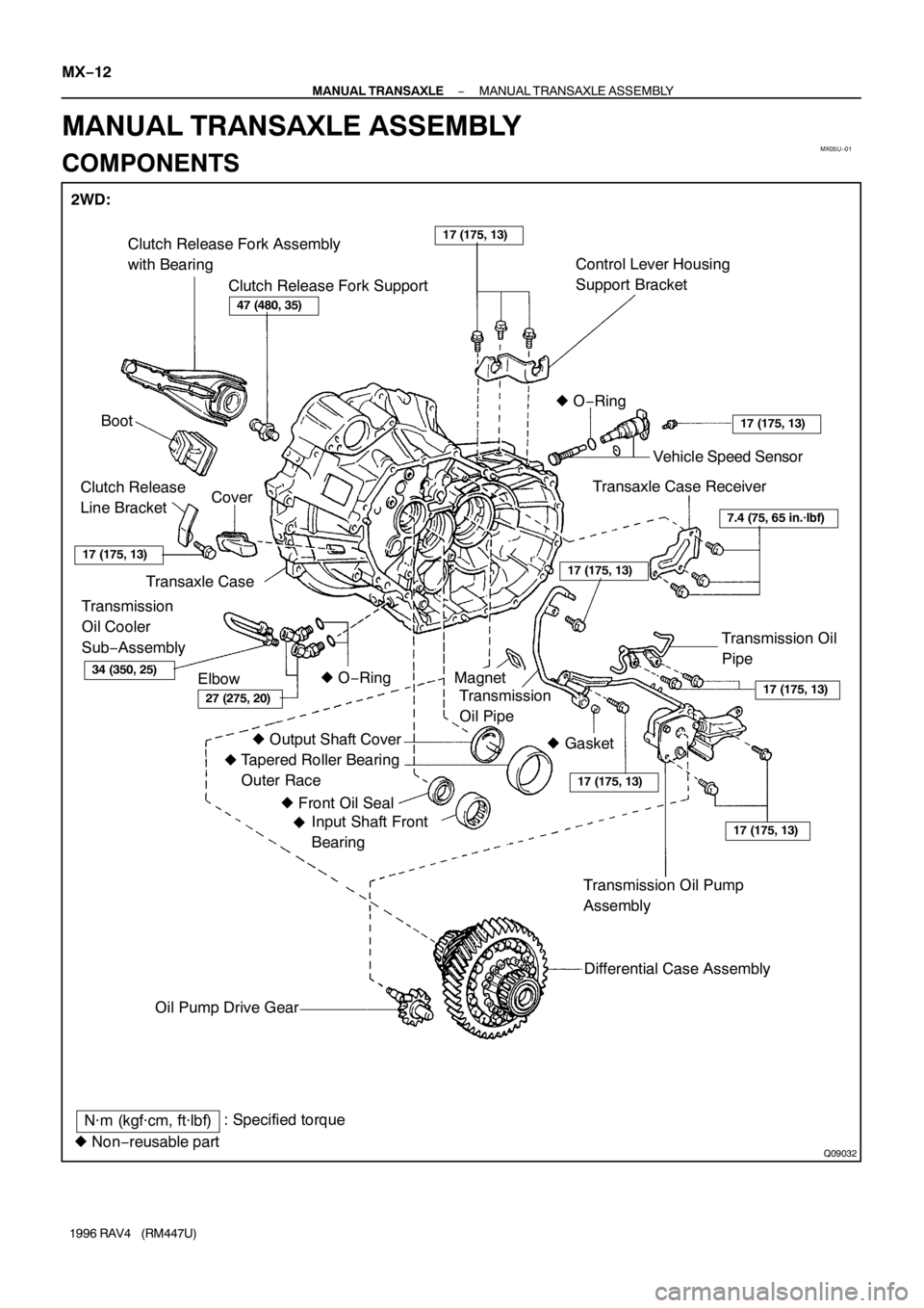
2WD:
Clutch Release Fork Assembly
with Bearing
Clutch Release Fork SupportControl Lever Housing
Support Bracket
Boot� O−Ring
Cover Clutch Release
Line Bracket
Transaxle Case
Transmission
Oil Cooler
Sub−Assembly
Elbow� O−RingVehicle Speed Sensor
Transaxle Case Receiver
Transmission Oil
Pipe
Magnet
Transmission
Oil Pipe
� Output Shaft Cover
Tapered Roller Bearing
Outer Race
� Front Oil Seal
Input Shaft Front
Bearing
Transmission Oil Pump
Assembly
Differential Case Assembly
Oil Pump Drive Gear
17 (175, 13)
47 (480, 35)
34 (350, 25)
27 (275, 20)
7.4 (75, 65 in.·lbf)
17 (175, 13)
17 (175, 13)
17 (175, 13)
17 (175, 13)
17 (175, 13)
17 (175, 13)
N·m (kgf·cm, ft·lbf): Specified torque
� Non−reusable part� Gasket
� � MX−12
− MANUAL TRANSAXLEMANUAL TRANSAXLE ASSEMBLY
1996 RAV4 (RM447U)
MANUAL TRANSAXLE ASSEMBLY
COMPONENTS
Page 1008 of 1354
Q09033
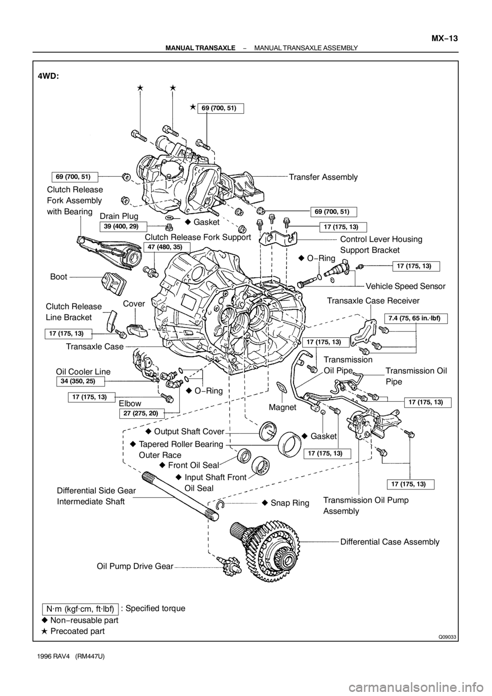
Clutch Release
Fork Assembly
with Bearing
Clutch Release Fork Support
Control Lever Housing
Support Bracket
Boot� O−Ring
Cover
Clutch Release
Line Bracket
Transaxle Case
Elbow� O−RingVehicle Speed Sensor
Transaxle Case Receiver
Transmission Oil
Pipe
Magnet
� Output Shaft Cover
� Tapered Roller Bearing
Outer Race
� Front Oil Seal
� Input Shaft Front
Oil Seal
Transmission Oil Pump
Assembly
Differential Case Assembly
Oil Pump Drive Gear
34 (350, 25)
27 (275, 20)
7.4 (75, 65 in.·lbf)
17 (175, 13)
17 (175, 13)
17 (175, 13)
17 (175, 13)
17 (175, 13)
17 (175, 13)
N·m (kgf·cm, ft·lbf): Specified torque
� Non−reusable part
� Precoated part 4WD:
�
�
Transfer Assembly
Transmission
Oil Pipe
17 (175, 13)
17 (175, 13)
69 (700, 51)
69 (700, 51)
39 (400, 29)
47 (480, 35)
Differential Side Gear
Intermediate Shaft
� Snap Ring
69 (700, 51)
Drain Plug
Oil Cooler Line� Gasket
� Gasket �
− MANUAL TRANSAXLEMANUAL TRANSAXLE ASSEMBLY
MX−13
1996 RAV4 (RM447U)
Page 1009 of 1354
: Specified torque
� Non−reusable part
� Precoated partTransmission Case Cover Transmission CaseNo.2 Selecting Bellcrank with
Selecting Bellcrank Support Shift and Se")
Q09034
�
N·m (kgf·cm, ft·lbf): Specified torque
� Non−reusable part
� Precoated partTransmission Case Cover Transmission CaseNo.2 Selecting Bellcrank with
Selecting Bellcrank Support Shift and Select Lever
Shaft Assembly
No.1 Oil Receiver Pipe Reverse Restrict
Pin� Straight Screw PlugBack−Up Light SwitchNo.3 Shift Fork No.3 Shift Fork ShaftInterlock Roller
Snap RingShift Head
Shift and Select Lever
Shaft Lock BoltNo.2 Shift Fork Shaft� Straight Screw Plug Reverse Shift Arm Bracket Assembly
Snap Ring
Reverse Shift Fork
No.1 Shift Fork
No.1 Shift Fork Shaft Seat
Spring
Ball
Slotted Spring
PinSnap RingSnap Ring
No.2 Shift Fork
No.2 Oil Receiver Pipe
Drain Plug Filler Plug
x10 x17�
�
��
24 (240, 17)
25 (250, 18)
25 (250, 18)
24 (240, 17)
24 (240, 17)
�25 (250, 18)
17 (175, 13)
40 (410, 30)
13 (130, 9)49 (500, 36)20 (200, 14)
17 (175, 13)
29 (300, 22)
49 (500, 36)
20 (200, 14)
49 (500, 36)
49 (500, 36)
29 (300, 22)
Breather Plug� Gasket � Gasket�
� Gasket � Gasket� Gasket
� Gasket MX−14
− MANUAL TRANSAXLEMANUAL TRANSAXLE ASSEMBLY
1996 RAV4 (RM447U)

Ex. Except
FWD Front Wheel Drive V")

1996 RAV4 (RM447U)
(f) Check the fluid leaks.
Check for leaks in the transmission and transfe")

1996 RAV4 (RM447U)
(b) Pull straight until there is a gap of about 60−80 mm
(2.4−3.1 in.) between the engine and tran")