Page 329 of 1354
P00495
Outside
Inside
− DIAGNOSTICSENGINE
DI−9
1996 RAV4 (RM447U)
4 Check air filter.
PREPARATION:
Remove air filter.
CHECK:
Visually check that the air cleaner element is not excessively
dirty or oily.
HINT:
If necessary, clean element with compressed air.
First blow from inside thoroughly,then blow from outside of ele-
ment.
NG Repair or replace.
OK
5 Check idle speed.
PREPARATION:
(a) Warm up engine to normal operating temperature.
(b) Switch off all accessories.
(c) Switch off air conditioning.
(d) Shift transmission into ”N” position.
(e) Connect the OBDII scan tool or TOYOTA hand−held tes-
ter to DLC3 on the vehicle.
CHECK:
Use CURRENT DATA to check the engine idle speed.
OK:
Idling speed: 650 − 750 rpm
NG Proceed to matrix chart of problem symptoms
on page DI−20.
OK
Page 502 of 1354
D00697
Ok if hot
Add if hot
AT4252
0 − 1 mm
D02248
DI−182
− DIAGNOSTICSAUTOMATIC TRANSAXLE (A540H)
1996 RAV4 (RM447U)
(f) Check the fluid leaks.
Check for leaks in the transmission and transfer.
If there are leaks, it is necessary to repair or replace O − rings,
FIPG’s, oil seals or other parts.
(g) Inspect and adjust the throttle cable.
(1) Check that the throttle valve is fully closed.
(2) Check that the inner cable is not slack.
(3) Loosen the adjustment nuts.
(4) Adjust the outer cable so that the distance between
the end of the boot and stopper on the cable is as
standard.
Standard boot and cable stopper distance:
0 − 1 mm (0 − 0.04 in.)
(5) Tighten the adjusting nuts.
(6) Recheck the adjustments.
(h) Adjust the shift control cable.
(1) Loosen the nut on the lever.
(2) Push the manual lever fully toward the right side of
the vehicle.
Page 957 of 1354

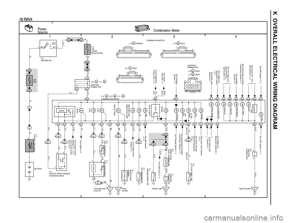
K OVERALL ELECTRICAL WIRING DIAGRAM
1
234
18 RAV4
Power
SourceCombination Meter2ACC
IG 1 AM1 4
2
1
2 1D 91E 8
21B 8
1K 47
1D1
1F
8A
11A 10A 2A 6C 6B 13A 12A 5B 9A 8B 7B
2IG19IG2
10 IG25 ID1 9 ID1 7 IG2
6 IG2 5 IG2B 4
100A ALT
3
F 8
10A
GAUGE
[FUSE BLOCK]
F 7
FUSIBLE LINK BLOCKW 1
WATER TEMP.
SEND ER
From Engine Control
Module< 2-2 < 4-4
From C ruise C ontrol
ECU< 13-4From Engine Contro
Module< 2-3 See ABS System
<17-3See SRS System< 11-2
SPEED
TACHOFU EL FU EL WATER TEMP. MALFUNCTION
INDICATO R LAM POIL ABS
4 B
R- L
WWWR-LL- B R- Y V-WR-L Y-RBR
BR Y- G G-RY-R
R- L R-L R- L
I1 0
IG NIT IO N S W
, C1 1 C
2
111
IF EC ID110
Intake
manifold Instrument panel
brace RH V 2
VEHICLE SPEED SENSOR
(
C o mbina tion M et er)COM B INA T IO N M ET E R C 9 A , J 1 1 B
F11
FUEL SENDER(
Main) F12
FUEL SENDER(
Sub) B 2
BRAKE FLUID
LEVEL WARNING SW
3
2 1
3
R-L L- B R- YR- L Y-R Y-B
BRBR BR Y-GY-R
BATTER Y
BR9C 2C 3C7A 9B 1B 4A 3A 13B
7C 8C 5A 10B 11B B C2B
17 IG2 1B 19
S ee Charging
System< 1-4
BR AKE BU ZZER
S ee E lectronically C ontrolled
Transmission S ystem< 4- 4S e e C ente r D iff. L o ck
(
M/T)
System< 11-4
S ee Headlight
System< 3-4
See Turn Signal and
Hazard Warning
Light System< 7-2 See SRS System< 11-2
S ee Interior Light
System< 6-2
S ee C harging S ys tem< 1- 4 S ee Ele ctr on ic ally C o ntr olled
T ransmission System< 4-4S ee Inte rior Lig ht
System<6-2
R- B W-B
R
(
4W D A /T)
1I 1J
O 1
OIL PRESSURE SW
1
EAIG R adiator rightRight kick panel
P 2
PARKING BRAKE SW1
A 5
A/T FLU ID TEM P. SW
1 2
R-BW-B RW-B
(
4WD A/T)
R-B
2124
1 40A
AM 1
6
B
F ro m Ig nite r< 5- 4
B-Y
10 13 9 8 7 6 5 4 3 2 1101112 139 8 7 6 5 4 3 2 1101112
10 9 8 7 6 5 4 3 2 1B C10 BLUE A C 9 BROWN
C C11 GRAYCO M BINATION M ETER
W-B
CA
BB BBJ10 A
JUNCTION
CONNECTOR
3B
BU LB C HEC K From C lutch
Start SW< 1-2B-W
A AA
A
J 1
JU NC TIO N
CONNECTOR J10
JUNCTION
CONNECTOR
From ABS ECU< 17-4 R-B
C 5S ee U nlock and S eat
B elt W arning S ystem
<3-2
C
ASee Taillight and
Illu min ation Sy ste m
<8-3S ee Ta illig h t a n d
Illumination System< 8- 3
10
1 A
S ee C ruise Control S ystem
<13-36 , C10 B
TUR N LH TUR N RH
HIGH BEAM
ECT PW R C. D IFF
LO C KSRS
ILLUMINATION
OPEN DOOR
CHARGE O/D
OFF A/T OIL
TEM P. BELT CRUISE
AAAAAA
BBBCCCA J10 G R A Y
J11 B G R A Y JUNCTION
CONNECTOR
(M /T )
(
A/T) B
From P a rk/N eu tra l
Position SW <1-315
Page 1007 of 1354
MX05U−01
Q09032
2WD:
Clutch Release Fork Assembly
with Bearing
Clutch Release Fork SupportControl Lever Housing
Support Bracket
Boot� O−Ring
Cover Clutch Release
Line Bracket
Transaxle Case
Transmission
Oil Cooler
Sub−Assembly
Elbow� O−RingVehicle Speed Sensor
Transaxle Case Receiver
Transmission Oil
Pipe
Magnet
Transmission
Oil Pipe
� Output Shaft Cover
Tapered Roller Bearing
Outer Race
� Front Oil Seal
Input Shaft Front
Bearing
Transmission Oil Pump
Assembly
Differential Case Assembly
Oil Pump Drive Gear
17 (175, 13)
47 (480, 35)
34 (350, 25)
27 (275, 20)
7.4 (75, 65 in.·lbf)
17 (175, 13)
17 (175, 13)
17 (175, 13)
17 (175, 13)
17 (175, 13)
17 (175, 13)
N·m (kgf·cm, ft·lbf): Specified torque
� Non−reusable part� Gasket
� � MX−12
− MANUAL TRANSAXLEMANUAL TRANSAXLE ASSEMBLY
1996 RAV4 (RM447U)
MANUAL TRANSAXLE ASSEMBLY
COMPONENTS
Page 1008 of 1354
Q09033
Clutch Release
Fork Assembly
with Bearing
Clutch Release Fork Support
Control Lever Housing
Support Bracket
Boot� O−Ring
Cover
Clutch Release
Line Bracket
Transaxle Case
Elbow� O−RingVehicle Speed Sensor
Transaxle Case Receiver
Transmission Oil
Pipe
Magnet
� Output Shaft Cover
� Tapered Roller Bearing
Outer Race
� Front Oil Seal
� Input Shaft Front
Oil Seal
Transmission Oil Pump
Assembly
Differential Case Assembly
Oil Pump Drive Gear
34 (350, 25)
27 (275, 20)
7.4 (75, 65 in.·lbf)
17 (175, 13)
17 (175, 13)
17 (175, 13)
17 (175, 13)
17 (175, 13)
17 (175, 13)
N·m (kgf·cm, ft·lbf): Specified torque
� Non−reusable part
� Precoated part 4WD:
�
�
Transfer Assembly
Transmission
Oil Pipe
17 (175, 13)
17 (175, 13)
69 (700, 51)
69 (700, 51)
39 (400, 29)
47 (480, 35)
Differential Side Gear
Intermediate Shaft
� Snap Ring
69 (700, 51)
Drain Plug
Oil Cooler Line� Gasket
� Gasket �
− MANUAL TRANSAXLEMANUAL TRANSAXLE ASSEMBLY
MX−13
1996 RAV4 (RM447U)
Page 1009 of 1354

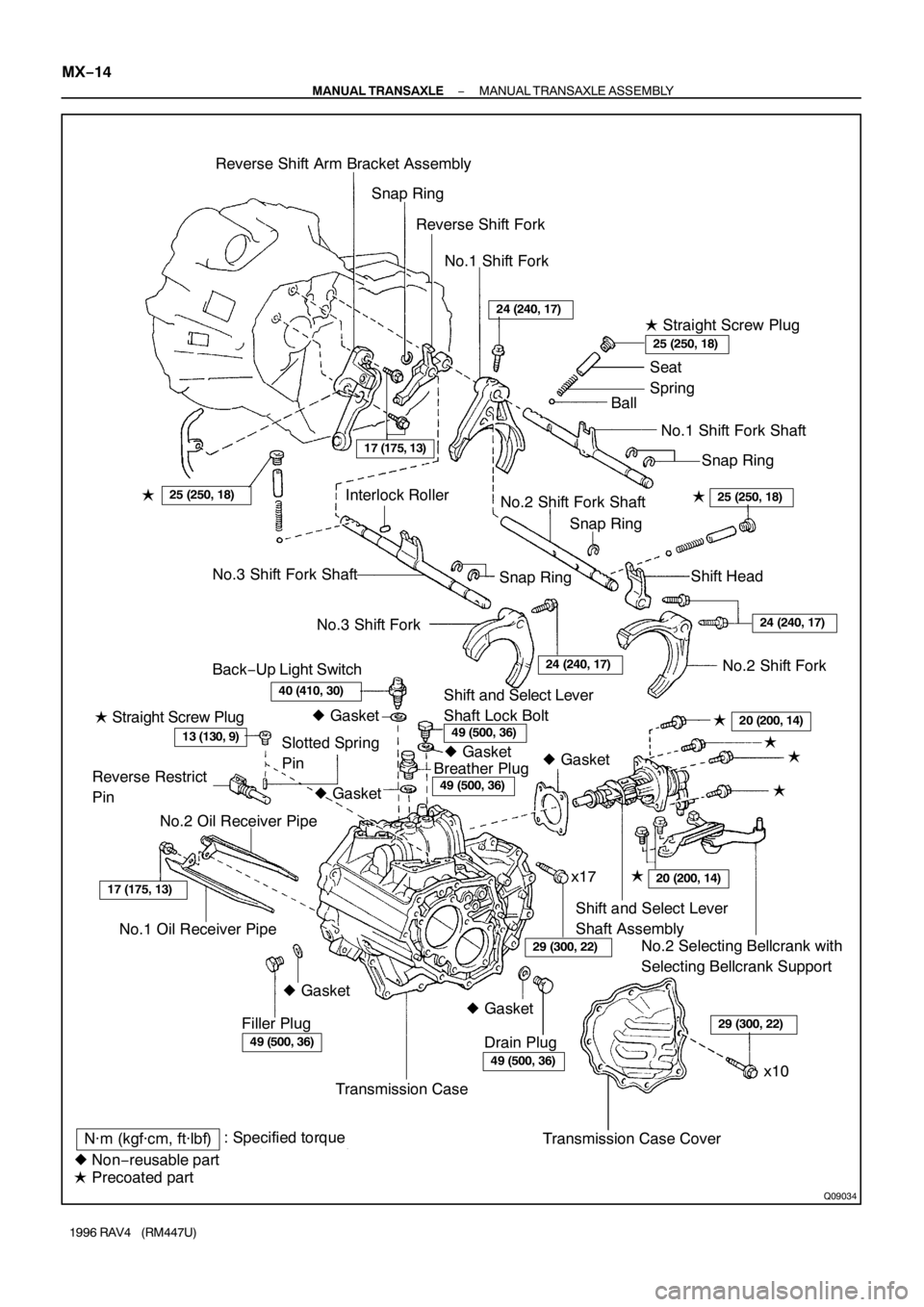
Q09034
�
N·m (kgf·cm, ft·lbf): Specified torque
� Non−reusable part
� Precoated partTransmission Case Cover Transmission CaseNo.2 Selecting Bellcrank with
Selecting Bellcrank Support Shift and Select Lever
Shaft Assembly
No.1 Oil Receiver Pipe Reverse Restrict
Pin� Straight Screw PlugBack−Up Light SwitchNo.3 Shift Fork No.3 Shift Fork ShaftInterlock Roller
Snap RingShift Head
Shift and Select Lever
Shaft Lock BoltNo.2 Shift Fork Shaft� Straight Screw Plug Reverse Shift Arm Bracket Assembly
Snap Ring
Reverse Shift Fork
No.1 Shift Fork
No.1 Shift Fork Shaft Seat
Spring
Ball
Slotted Spring
PinSnap RingSnap Ring
No.2 Shift Fork
No.2 Oil Receiver Pipe
Drain Plug Filler Plug
x10 x17�
�
��
24 (240, 17)
25 (250, 18)
25 (250, 18)
24 (240, 17)
24 (240, 17)
�25 (250, 18)
17 (175, 13)
40 (410, 30)
13 (130, 9)49 (500, 36)20 (200, 14)
17 (175, 13)
29 (300, 22)
49 (500, 36)
20 (200, 14)
49 (500, 36)
49 (500, 36)
29 (300, 22)
Breather Plug� Gasket � Gasket�
� Gasket � Gasket� Gasket
� Gasket MX−14
− MANUAL TRANSAXLEMANUAL TRANSAXLE ASSEMBLY
1996 RAV4 (RM447U)
Page 1015 of 1354

MT0693
SST
Q06375
Z17557
Matchmarks
Q01614
Q08124
MX−20
− MANUAL TRANSAXLEMANUAL TRANSAXLE ASSEMBLY
1996 RAV4 (RM447U)
23. REMOVE OUTPUT SHAFT REAR TAPER ROLLER
BEARING OUTER RACE
Using SST and a hammer, remove the output shaft rear taper
roller bearing outer race.
SST 09316−60011 (09316−00011)
24. REMOVE TRANSMISSION OIL PIPE
(a) Remove the gasket from the oil pipe.
(b) Remove the 2 bolts and oil pipe.
Torque: 17 N·m (175 kgf·cm, 13 ft·lbf)
25. REMOVE REVERSE SHIFT ARM BRACKET AS-
SEMBLY
Remove the bolt and pull off the reverse shift arm and bracket.
Torque: 17 N·m (175 kgf·cm, 13 ft·lbf)
26. REMOVE REVERSE IDLER GEAR AND SHAFT
Pull out the shaft, remove the reverse idler gear and thrust
washer.
HINT:
At the time of reassembly, please refer to the following item.
Align the matchmarks, as shown.
27. REMOVE STRAIGHT SCREW PLUG, LOCKING BALL
AND SPRING
(a) Using a hexagon wrench (6 mm), remove the 2 plugs.
Sealant:
Part No. 08833−00080, THREE BOND 1344, LOCTITE
242 or equivalent
Torque: 25 N·m (250 kgf·cm, 18 ft·lbf)
(b) Using a magnetic finger, remove the 2 seats, springs and
balls.
28. REMOVE NO.1, NO.2 SHIFT FORKS AND SHIFT HEAD
SET BOLT
Torque: 24 N·m (240 kgf·cm, 17 ft·lbf)
29. REMOVE NO.1 SHIFT FORK SHAFT
Pull up the No.3 shift fork shaft, remove the No.1 shift fork shaft.
HINT:
At the time of reassembly, please refer to the following item.
When it is difficult to push the fork shaft through the reverse shift
fork, pull up the No.3 shift fork shaft.
Page 1016 of 1354

Q08125
Q08126
Z00182
− MANUAL TRANSAXLEMANUAL TRANSAXLE ASSEMBLY
MX−21
1996 RAV4 (RM447U)
30. REMOVE INTERLOCK ROLLER
Using a magnetic finger, remove the interlock roller from the re-
verse shift fork.
31. REMOVE NO.2 SHIFT FORK SHAFT, SHIFT HEAD
AND NO.1 SHIFT FORK
(a) Pull out the No.2 shift fork shaft.
(b) Remove the shift head and No.1 shift fork.
32. REMOVE NO.3 SHIFT FORK SHAFT WITH REVERSE
SHIFT FORK AND NO.2 SHIFT FORK
(a) Pull out the No.3 shift fork shaft with the reverse shift fork.
(b) Remove the No.2 shift fork.
33. REMOVE SNAP RING
(a) Using 2 screwdrivers and a hammer, remove the snap
ring and reverse shift fork from the No.3 shift fork shaft.
(b) Using 2 screwdrivers and a hammer, remove the 3 snap
rings from the No.1, No.2 and No.3 shift fork shafts.
34. REMOVE INPUT AND OUTPUT SHAFTS ASSEMBLY
(a) Leaning the output shaft to the differential side, remove
the input shaft assembly.
(b) Lift up the differential case assembly, remove the output
shaft assembly.
35. REMOVE DIFFERENTIAL CASE ASSEMBLY
(a) Remove the oil pump drive gear.
(b) Remove the differential case assembly.
36. REMOVE MAGNET FROM TRANSAXLE CASE
37. REMOVE TRANSMISSION OIL PUMP ASSEMBLY
AND OIL PIPE
(a) Remove the 2 bolts and oil pipe.
Torque: 17 N·m (175 kgf·cm, 13 ft·lbf)
(b) Remove the 2 bolts and oil pump assembly.
Torque: 17 N·m (175 kgf·cm, 13 ft·lbf)