Page 6 of 1354
AT8584
AT8586
Z11664
B A
B
B A
B A
A A CA
AT3327
Q06411
BA AX−6
− AUTOMATIC TRANSAXLE (A241E)VALVE BODY ASSEMBLY
1996 RAV4 (RM447U)
6. REMOVE MANUAL DETENT SPRING
Remove the bolt and manual detent spring.
7. REMOVE 3 SOLENOID CONNECTORS
8. REMOVE VALVE BODY
(a) Disconnect the throttle cable.
(b) Remove the 11 bolts and wire retainer.
Bolt length:
Bolt A: 20 mm (0.79 in.)
Bolt B: 30 mm (1.18 in.)
Bolt C: 55 mm (2.17 in.)
(c) Disconnect the manual valve connecting rod.
(d) Remove the valve body.
9. REMOVE 3 SOLENOID VALVES
(a) Remove the 3 solenoid valves.
(b) Remove the O−rings from each of the solenoid valves.
10. INSTALL SHIFT SOLENOID VALVE
(a) Coat new O−rings with ATF and install them to the each
of the solenoid valve.
(b) Install the 3 shift solenoid valves with the 2 bolts.
Torque:
Bolt A: 6.4 N·m (65 kgf·cm, 56 in.·lbf)
Bolt B: 10 N·m (100 kgf·cm, 7 ft·lbf)
Page 7 of 1354
AT3327
Z11664
B A
B
B A
B A
A A C
AT8586
AT8584
Q06418
− AUTOMATIC TRANSAXLE (A241E)VALVE BODY ASSEMBLY
AX−7
1996 RAV4 (RM447U)
11. INSTALL VALVE BODY
(a) Install the valve body.
(b) Connect the manual valve connecting rod.
(c) Install the 17 bolts and wire retainer.
Bolt length:
Bolt A: 20 mm (0.79 in.)
Bolt B: 30 mm (1.18 in.)
Bolt C: 55 mm (2.17 in.)
Torque: 10 N·m (100 kgf·cm, 7 ft·lbf)
(d) Connect the throttle cable.
12. CONNECT 3 SOLENOID CONNECTORS
13. INSTALL MANUAL DETENT SPRING
Install the manual detent spring with the bolt.
Torque: 10 N·m (100 kgf·cm, 7 ft·lbf)
HINT:
Check that the manual valve lever is in contact with the center
of the roller at the tip of the detent spring.
14. INSTALL OIL PIPE CLAMP AND OIL PIPES
(a) Install the 5 pipes with a large screwdriver.
(b) Install the oil pump clamp with the bolt.
Torque: 10 N·m (100 kgf·cm, 7 ft·lbf)
Page 9 of 1354
Q06117
AX055−02
AT5641
Q057310.8−1.5 mm (0.031−0.059 in.) 200 mm (7.87 in.)
− AUTOMATIC TRANSAXLE (A241E)THROTTLE CABLE
AX−9
1996 RAV4 (RM447U)
THROTTLE CABLE
ON−VEHICLE REPAIR
1. DISCONNECT THROTTLE CABLE FROM ENGINE
2. REMOVE NO.2 ENGINE UNDER COVER
3. REMOVE PARK/NEUTRAL POSITION SWITCH (See
page AX−4)
4. REMOVE VALVE BODY (See page AX−5)
5. REMOVE THROTTLE CABLE
(a) Remove the retaining bolt and plate.
(b) Pull out the cable from the transaxle case.
6. INSTALL THROTTLE CABLE
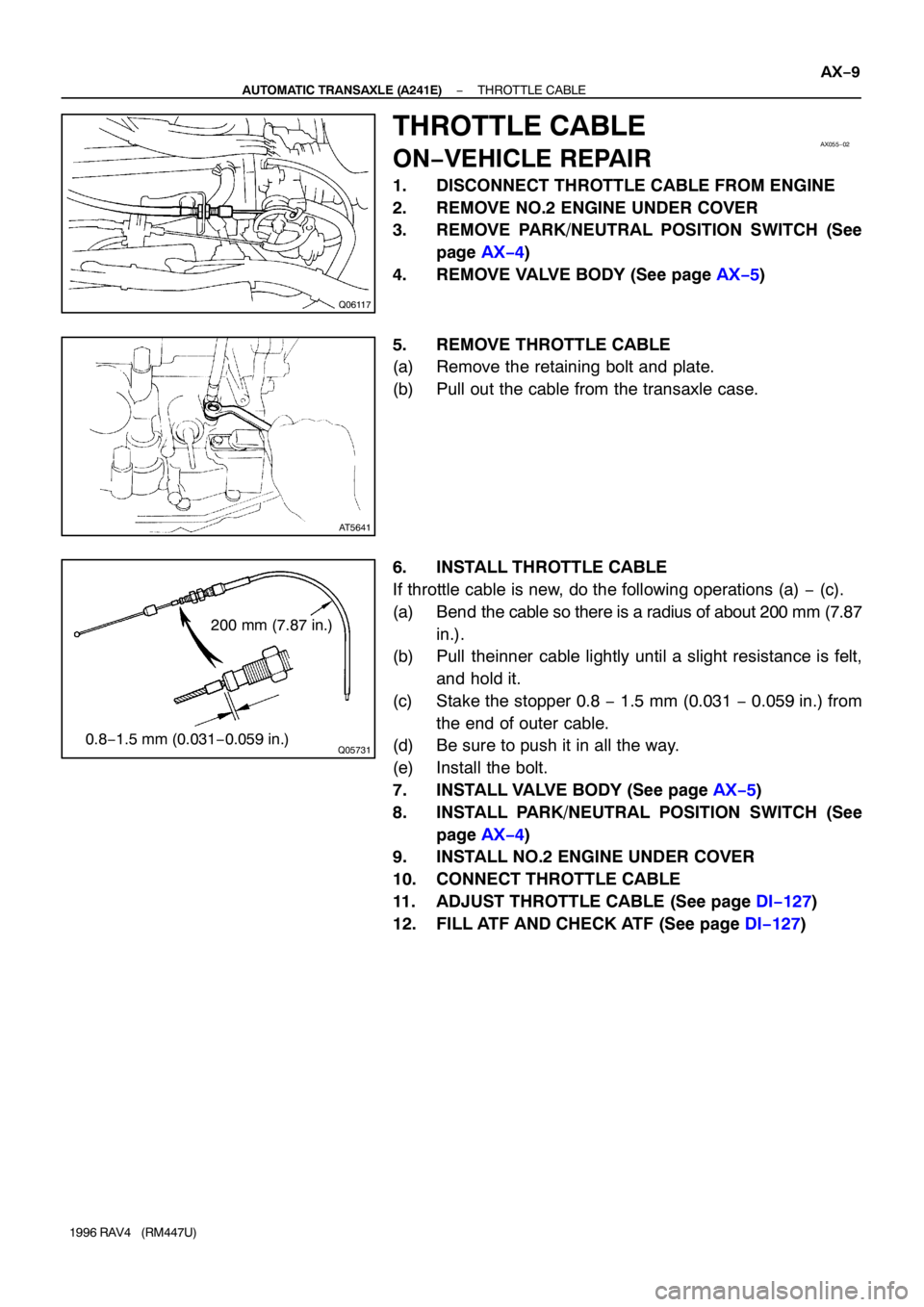
If throttle cable is new, do the following operations (a) − (c).
(a) Bend the cable so there is a radius of about 200 mm (7.87
in.).
(b) Pull theinner cable lightly until a slight resistance is felt,
and hold it.
(c) Stake the stopper 0.8 − 1.5 mm (0.031 − 0.059 in.) from
the end of outer cable.
(d) Be sure to push it in all the way.
(e) Install the bolt.
7. INSTALL VALVE BODY (See page AX−5)
8. INSTALL PARK/NEUTRAL POSITION SWITCH (See
page AX−4)
9. INSTALL NO.2 ENGINE UNDER COVER
10. CONNECT THROTTLE CABLE
11. ADJUST THROTTLE CABLE (See page DI−127)
12. FILL ATF AND CHECK ATF (See page DI−127)
Page 31 of 1354
D00694
OR0038
Z13387A B CDC
C
D00696
AX−10
− AUTOMATIC TRANSAXLE (A540H)VALVE BODY ASSEMBLY
1996 RAV4 (RM447U)
11. REMOVE VALVE BODY
(a) Remove the 10 bolts.
(b) Disconnect the throttle cable from the cam and remove
the valve body.
12. INSTALL VALVE BODY TO TRANSAXLE CASE
(a) While holding the cam down with your hand, slip the cable
end into the slot.
(b) Raise up the valve body into place.
NOTICE:
Do not entangle the solenoid wire.
(c) Install and tighten the 10 bolts.
Torque: 11 N·m (110 kgf·cm, 8 ft·lbf)
HINT:
�Each bolt length is indicated below.
�Hand−tighten the 10 bolts first, then torque with a torque
wrench.
Bolt length:
Bolt A: 22 mm (0.87 in.)
Bolt B: 32 mm (1.26 in.)
Bolt C: 43 mm (1.69 in.)
Bolt D: 55 mm (2.17 in.)
13. INSTALL B
3 APPLY PIPE
NOTICE:
Be careful not to bend or damage the pipe.
Page 34 of 1354
Q06117
AX04R−02
Q06068
Q057310.8 − 1.5 mm (0.031 − 0.059 in.) 200 mm
(7.87 in.)
− AUTOMATIC TRANSAXLE (A540H)THROTTLE CABLE
AX−13
1996 RAV4 (RM447U)
THROTTLE CABLE
ON−VEHICLE REPAIR
1. DISCONNECT THROTTLE CABLE FROM LINKAGE
2. REMOVE PARK/NEUTRAL POSITION SWITCH
(See page AX−6)
3. REMOVE VALVE BODY
(See page AX−8)
4. REMOVE THROTTLE CABLE
(a) Remove the bolt and pull the cable out of the transaxle
case.
(b) Remove the O−ring from the throttle cable.
5. INSTALL THROTTLE CABLE INTO TRANSAXLE
CASE
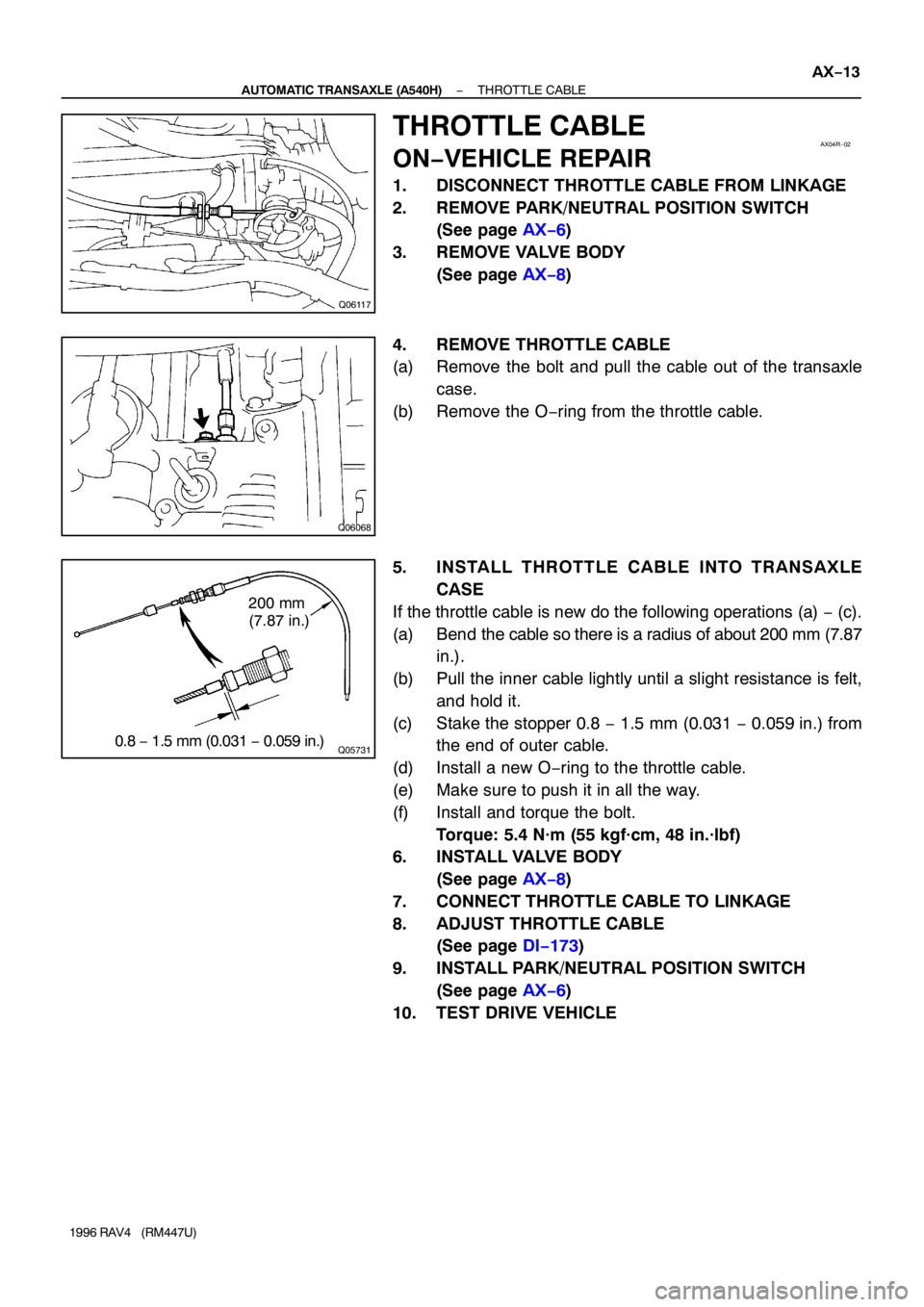
If the throttle cable is new do the following operations (a) − (c).
(a) Bend the cable so there is a radius of about 200 mm (7.87
in.).
(b) Pull the inner cable lightly until a slight resistance is felt,
and hold it.
(c) Stake the stopper 0.8 − 1.5 mm (0.031 − 0.059 in.) from
the end of outer cable.
(d) Install a new O−ring to the throttle cable.
(e) Make sure to push it in all the way.
(f) Install and torque the bolt.
Torque: 5.4 N·m (55 kgf·cm, 48 in.·lbf)
6. INSTALL VALVE BODY
(See page AX−8)
7. CONNECT THROTTLE CABLE TO LINKAGE
8. ADJUST THROTTLE CABLE
(See page DI−173)
9. INSTALL PARK/NEUTRAL POSITION SWITCH
(See page AX−6)
10. TEST DRIVE VEHICLE
Page 354 of 1354

P24296
Throtttle Position
SensorECM
VC
VTA
E2 DI−34
− DIAGNOSTICSENGINE
1996 RAV4 (RM447U)
DTC P0120 Throttle/Pedal Position Sensor/Switch ”A”
Circuit Malfunction
CIRCUIT DESCRIPTION
The throttle position sensor is mounted in the throttle body and
detects the throttle valve opening angle. When the throttle valve
is fully closed, a voltage of approximately 0.3 V − 0.8 V is ap-
plied to terminal VTA of the ECM. The voltage applied to the ter-
minal VTA of the ECM increases in proportion to the opening
angle of the throttle valve and becomes approximately 3.2 − 4.9
V when the throttle valve is fully opened. The ECM judges the
vehicle driving conditions from this signal input from terminal
VTA, and uses them as one of the conditions for deciding the
air−fuel ration correction, power increases correction and fuel−
cut control etc.
DTC No.DTC Detecting ConditionTrouble Area
P0120
Condition (a) or (b) continues
(a) VTA < 0.1 V
(b) VTA > 4.9 V�Open or short in throttle position sensor circuit
�Throttle position sensor
�ECM
HINT:
After confirming DTC P0120 use the OBDII scan tool or TOYOTA hand−held tester to confirm the throttle
valve opening percentage.
Throttle Valve opening position expressed as percentageTrouble AreaThrottle Valve fully closedThrottle Valve fully open
0 %0 %VC line open
VTA line open or short
100 %100 %E2 line open
DI3ZH−01
Page 356 of 1354
BE6653P23908
A06617
ON
A00400
ON
VTA
(+)E2
(−)
DI−36
− DIAGNOSTICSENGINE
1996 RAV4 (RM447U)
OK Check for intermittent problems
(See page DI−3).
NG
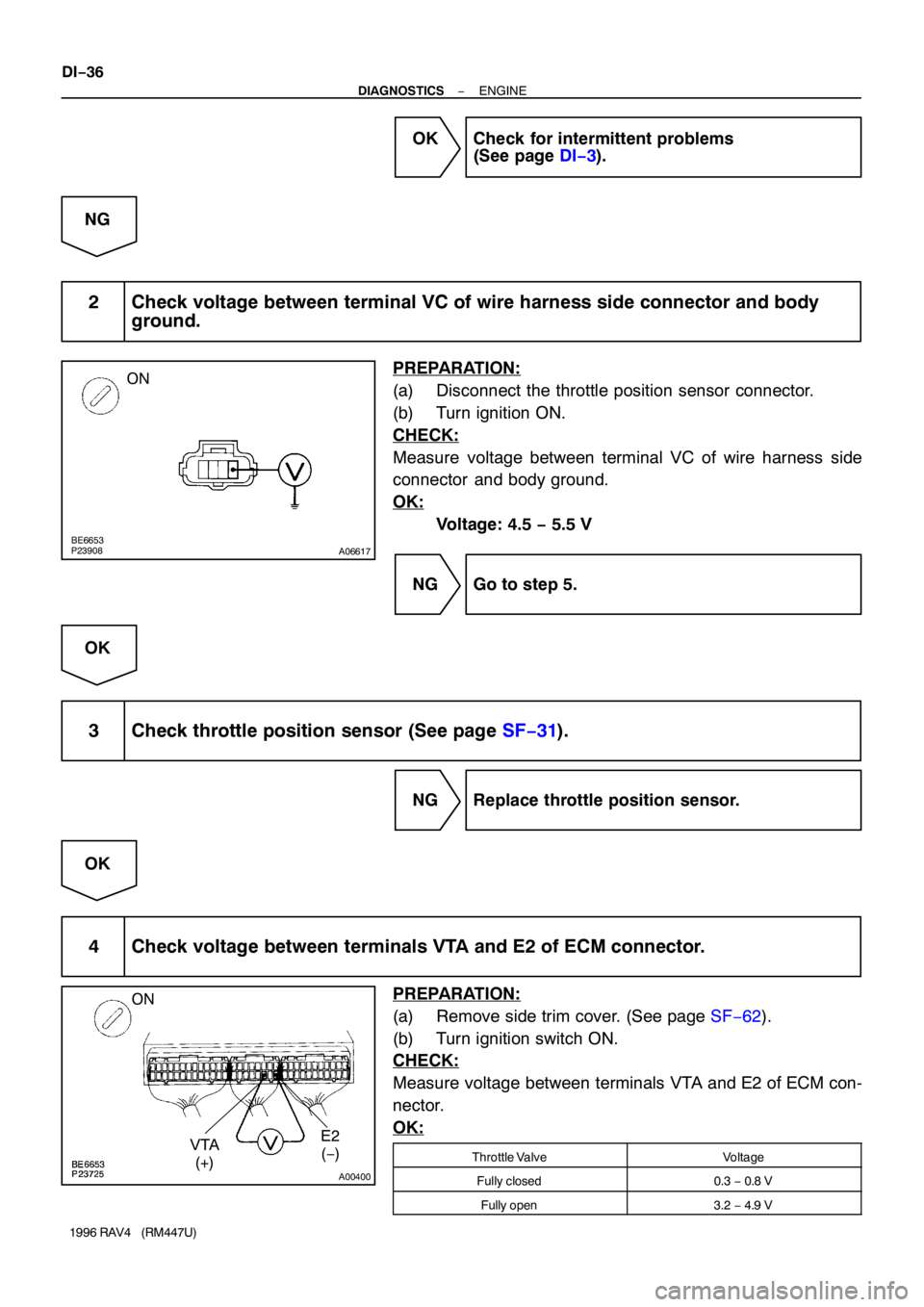
2 Check voltage between terminal VC of wire harness side connector and body
ground.
PREPARATION:
(a) Disconnect the throttle position sensor connector.
(b) Turn ignition ON.
CHECK:
Measure voltage between terminal VC of wire harness side
connector and body ground.
OK:
Voltage: 4.5 − 5.5 V
NG Go to step 5.
OK
3 Check throttle position sensor (See page SF−31).
NG Replace throttle position sensor.
OK
4 Check voltage between terminals VTA and E2 of ECM connector.
PREPARATION:
(a) Remove side trim cover. (See page SF−62).
(b) Turn ignition switch ON.
CHECK:
Measure voltage between terminals VTA and E2 of ECM con-
nector.
OK:
Throttle ValveVoltage
Fully closed0.3 − 0.8 V
Fully open3.2 − 4.9 V
Page 385 of 1354
P25430
Throttle Body
Exhaust GasEGR Valve
Diagram ECM
VSV
Throttle
Valve
Intake Air
Chamber
EGR
Vacuum
Modulator
S02387
From
Battery6
1J2
1
1E J/B No.1EFI Main Relay
Fuse Block
11
10E423
EA12 R/B No.6ECM
J1
Junction Connector
AA
W−B B−W VSV (for EGR)
2
1
B−O
IGNEGR
E01
EAFrom
IG Switch
B−O 666 3
125
R−W
B−RB−R
W−B
− DIAGNOSTICSENGINE
DI−65
1996 RAV4 (RM447U)
DTC P0401 Exhaust Gas Recirculation Flow Insufficient
Detected
CIRCUIT DESCRIPTION
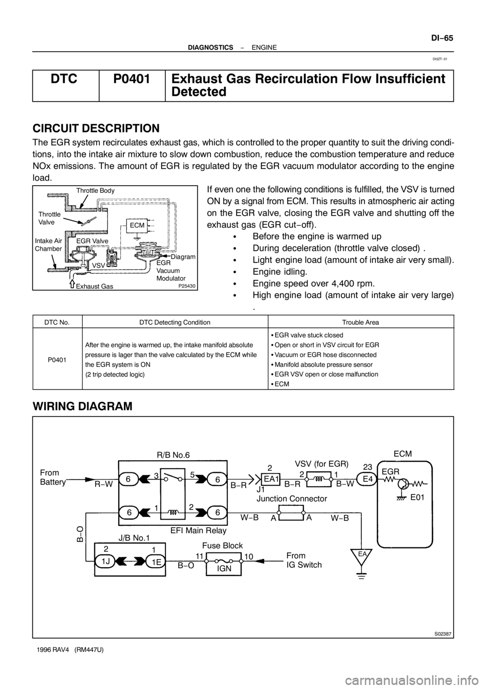
The EGR system recirculates exhaust gas, which is controlled to the proper quantity to suit the driving condi-
tions, into the intake air mixture to slow down combustion, reduce the combustion temperature and reduce
NOx emissions. The amount of EGR is regulated by the EGR vacuum modulator according to the engine
load.
If even one the following conditions is fulfilled, the VSV is turned
ON by a signal from ECM. This results in atmospheric air acting
on the EGR valve, closing the EGR valve and shutting off the
exhaust gas (EGR cut−off).
�Before the engine is warmed up
�During deceleration (throttle valve closed) .
�Light engine load (amount of intake air very small).
�Engine idling.
�Engine speed over 4,400 rpm.
�High engine load (amount of intake air very large)
.
DTC No.DTC Detecting ConditionTrouble Area
P0401
After the engine is warmed up, the intake manifold absolute
pressure is lager than the valve calculated by the ECM while
the EGR system is ON
(2 trip detected logic)
�EGR valve stuck closed
�Open or short in VSV circuit for EGR
�Vacuum or EGR hose disconnected
�Manifold absolute pressure sensor
�EGR VSV open or close malfunction
�ECM
WIRING DIAGRAM
DI3ZT−01