Page 2610 of 2890
B4M0915
10AK6
CHECK G SENSOR.
1) Remove console box.
2) Remove G sensor from vehicle.
3) Connect connector to G sensor.
4) Connect connector to ABSCM.
5) Turn ignition switch to ON.
6) Measure voltage between G sensor connector termi-
nals.
: Connector & terminal
(P11) No. 2 (+)—No.1(�)
Is voltage 2.3±0.2 V when G sensor is hori-
zontal?
: Go to next.
: Replace G sensor.
B4M0917A
: Connector & terminal
(P11) No. 2 (+)—No.1(�)
Is voltage 3.9±0.2 V when G sensor is
inclined forwards to 90°?
: Go to next.
: Replace G sensor.
B4M0918A
: Connector & terminal
(P11) No. 2 (+)—No.1(�)
Is voltage 0.7±0.2 V when G sensor is
inclined backwards to 90°?
: Go to step10AK7.
: Replace G sensor.
270
4-4cBRAKES [ABS 5.3 TYPE]
10. Diagnostics Chart with Select Monitor
Page 2611 of 2890
10AK7
CHECK ABSCM.
1) Connect all connectors.
2) Erase the memory.
3) Perform inspection mode.
4) Read out the trouble code.
: Is the same trouble code as in the current
diagnosis still being output?
: Replace ABSCM.
: Go to next.
: Are other trouble codes being output?
: Proceed with the diagnosis corresponding to the
trouble code.
: A temporary poor contact.
271
4-4cBRAKES [ABS 5.3 TYPE]
10. Diagnostics Chart with Select Monitor
Page 2612 of 2890

�ABS s")
11. General Diagnostics Table
A: SYMPTOMS AND PROBABLE CAUSES
Symptom Probable faulty units/parts
Vehicle instability during brakingVehicle pulls to either side.�Hydraulic unit (solenoid valve)
�ABS sensor
�Brake (caliper & piston, pads)
�Wheel alignment
�Tire specifications, tire wear and air pressures
�Incorrect wiring or piping connections
�Road surface (uneven, camber)
Vehicle spins.�Hydraulic unit (solenoid valve)
�ABS sensor
�Brake (pads)
�Tire specifications, tire wear and air pressures
�Incorrect wiring or piping connections
Poor brakingLong braking/stopping distance�Hydraulic unit (solenoid valve)
�Brake (pads)
�Air in brake line
�Tire specifications, tire wear and air pressures
�Incorrect wiring or piping connections
Wheel locks.�Hydraulic unit (solenoid valve, motor)
�ABS sensor
�Incorrect wiring or piping connections
Brake dragging�Hydraulic unit (solenoid valve)
�ABS sensor
�Master cylinder
�Brake (caliper & piston)
�Parking brake
�Axle & wheels
�Brake pedal play
Long brake pedal stroke�Air in brake line
�Brake pedal play
Vehicle pitching�Suspension play or fatigue (reduced damping)
�Incorrect wiring or piping connections
�Road surface (uneven)
Unstable or uneven braking�Hydraulic unit (solenoid valve)
�ABS sensor
�Brake (caliper & piston, pads)
�Tire specifications, tire wear and air pressures
�Incorrect wiring or piping connections
�Road surface (uneven)
Vibration and/or noise (while
driving on slippery roads)Excessive pedal vibration�Incorrect wiring or piping connections
�Road surface (uneven)
Noise from hydraulic unit�Hydraulic unit (mount bushing)
�ABS sensor
�Brake piping
Noise from front of vehicle�Hydraulic unit (mount bushing)
�ABS sensor
�Master cylinder
�Brake (caliper & piston, pads, rotor)
�Brake piping
�Brake booster & check valve
�Suspension play or fatigue
Noise from rear of vehicle�ABS sensor
�Brake (caliper & piston, pads, rotor)
�Parking brake
�Brake piping
�Suspension play or fatigue
272
4-4cBRAKES [ABS 5.3 TYPE]
11. General Diagnostics Table
Page 2613 of 2890
B: CHECKING THE HYDRAULIC UNIT
OPERATION
1) Do ABS sequence control patterns take place in correct
order?
If not, check wiring and piping for incorrect connections.
2) Are oil pressure or braking force variations within speci-
fications?
If not, check master cylinder, brake piping, hydraulic unit,
proportioning valve and wheel cylinder for improper opera-
tion.
3) Does pedal hardness change before and after ABS
sequence control?
If so, bleed air from brake line.
273
4-4cBRAKES [ABS 5.3 TYPE]
11. General Diagnostics Table
Page 2702 of 2890
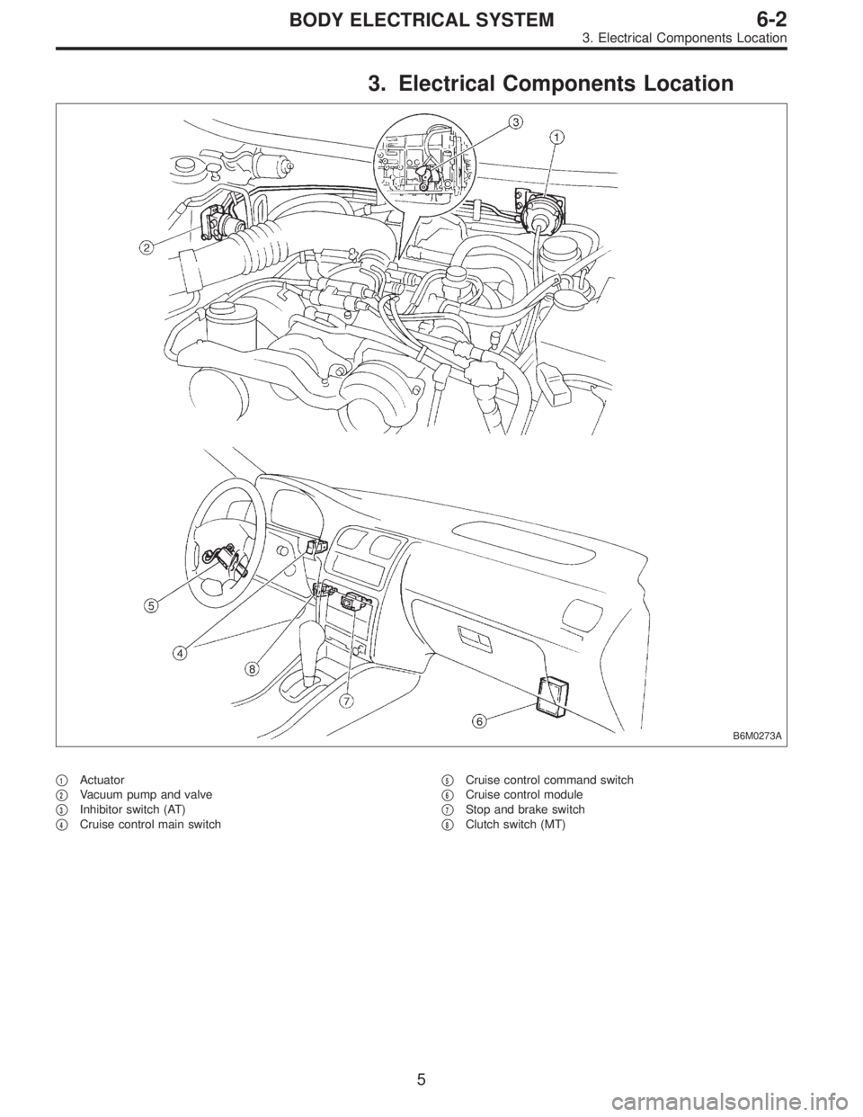
3. Electrical Components Location
B6M0273A
�1Actuator
�
2Vacuum pump and valve
�
3Inhibitor switch (AT)
�
4Cruise control main switch�
5Cruise control command switch
�
6Cruise control module
�
7Stop and brake switch
�
8Clutch switch (MT)
5
6-2BODY ELECTRICAL SYSTEM
3. Electrical Components Location
Page 2704 of 2890

Main power supply 2�Battery voltage is present when main power is tu")
5. Control Module I/O Signal
G6M0015
ContentTerminal
No.Measuring conditions and I/O signals (ignition switch ON and engine idling)
Main power supply 2�Battery voltage is present when main power is turned ON.
�“0”volt is present when main power is turned OFF.
Inhibitor switch (AT) (U.S.A.)
N position switch (AT) (CANADA)4�“0”volt is present when selector lever is set to P or N position (CANADA: N position only).
�Battery voltage is present when selector lever is other than P or N position (CANADA: N
position only).
Air valve 5�“0”volt is present when vehicle is stopped.
�ON-and-OFF (“0”-and-battery voltage) operation is alternately repeated while cruise control
is operating.
GND 6—
Vacuum pump motor 7�“0”volt is present when vehicle is stopped.
�ON-and-OFF (“0”-and-battery voltage) operation is alternately repeated while cruise control
is operating.
Data link connector 8—
RESUME/ACCEL switch 9�Battery voltage is present when switch is turned ON.
�“0”volt is present when switch is turned OFF.
SET/COAST switch 10�Battery voltage is present when switch is turned ON.
�“0”volt is present when switch is turned OFF.
Ignition switch 12�Battery voltage is present when ignition switch is turned ON.
�“0”volt is present when ignition switch is turned OFF.
Release valve 13�“0”volt is present when vehicle is stopped.
�ON-and-OFF (“0”-and-battery voltage) operation is alternately repeated while cruise control
is operating.
Power supply to vacuum pump
motor, air valve, release valve14�“0”volt is present when vehicle is stopped.
�Battery voltage is present while cruise control is operating.
Cruise main switch 15�Battery voltage is present during pressing the main switch, and then approx. 12 V is
present while switch is turned ON.
�“0”volt is present when switch is turned OFF.
Brake switch 16Turn the cruise main switch to ON and leave clutch pedal released (MT).
Then check that;
�“0”volt is present when brake pedal is depressed.
�Battery voltage is present when brake pedal is released.
Additionally only in MT vehicle, keep the cruise main switch to ON and leave brake pedal
released.
Then check that;
�“0”volt is present when clutch pedal is depressed.
�Battery voltage is present when clutch pedal is released.
Data link connector 17—
Data link connector 18—
Vehicle speed sensor 2 19Lift-up the vehicle until all four wheels are raised off ground, and then rotate any wheel manu-
ally.
Approx. 5 and 0 volt pulse signals are alternately input to cruise control module.
Stop light switch 20Turn ignition switch to OFF.
Then check that;
�Battery voltage is present when brake pedal is depressed.
�“0”volt is present when brake pedal is released.
NOTE:
Voltage at terminals 5, 7, 13 and 14 cannot be checked unless vehicle is driving by cruise control operation.
7
6-2BODY ELECTRICAL SYSTEM
5. Control Module I/O Signal
Page 2705 of 2890
![SUBARU LEGACY 1996 Service Repair Manual 6. Diagnostics Chart for On-board
Diagnosis System
A: BASIC DIAGNOSTICS PROCEDURE
Trouble occurs.
Pre-inspection <Ref. to 6-2 [T200].>
Check if cruise control main switch turns ON prop-
erly.
OK
�Not](/manual-img/17/57433/w960_57433-2704.png "SUBARU LEGACY 1996 Service Repair Manual 6. Diagnostics Chart for On-board
Diagnosis System
A: BASIC DIAGNOSTICS PROCEDURE
Trouble occurs.
Pre-inspection <Ref. to 6-2 [T200].>
Check if cruise control main switch turns ON prop-
erly.
OK
�Not")
6. Diagnostics Chart for On-board
Diagnosis System
A: BASIC DIAGNOSTICS PROCEDURE
Trouble occurs.
Pre-inspection
Check if cruise control main switch turns ON prop-
erly.
OK
�Not OK
Diagnostics Chart for Power Line
[T700].>
(Main switch fails when turning to ON.)
Check if cruise speed is properly set while driving at
minimum of 40 km/h (25 MPH).
OK
�Not OK
Diagnostics Chart with Trouble Code
[T800].> (When cruise control cannot be set.)
Check if cruise control is properly released during
operation.
OK
�Not OK
Check if cruise speed is held within set speed ±3
km/h (±2 MPH).
OK
�Not OK
Basic inspection of actuator, vacuum pump and
valve (When is not running
at a fixed speed.)
Check if RESUME/ACCEL switch functions properly.
OK
�Not OK
Diagnostics Chart with Trouble Code
[T800].> (When cruise control cannot be set.)
Check if SET/COAST switch functions properly.
OK
�Not OK
Check if CANCEL switch functions properly. (Airbag
equipped model)
OK
�Not OK
Check if cruise speed is released when brake pedal
is depressed.
OK
�Not OK
Set cruise speed again. Check if cruise speed is
released when clutch pedal is depressed (MT
model) or when select lever is moved to“Neutral.”
OK
�Not OK
Cruise control system is in good order.
�
�
�
�
�
�
�
�
�
�
�
8
6-2BODY ELECTRICAL SYSTEM
6. Diagnostics Chart for On-board Diagnosis System
Page 2707 of 2890
 Connect select monitor.
2) Start the engine and turn cruise control main switch to
ON.
3) Set select monitor in“FB0”mode.
4) Drive vehicle at least 40 km/h")
2. CRUISE CANCEL CONDITIONS DIAGNOSIS
1) Connect select monitor.
2) Start the engine and turn cruise control main switch to
ON.
3) Set select monitor in“FB0”mode.
4) Drive vehicle at least 40 km/h (25 MPH) with cruise
speed set.
5) If cruise speed is canceled itself (without doing any
cancel operations), a trouble code will appear on select
monitor display.
CAUTION:
�A trouble code will also appear when cruise cancel
is effected by driver. Do not confuse.
�Have a co-worker ride in vehicle to assist in diagno-
sis during driving.
NOTE:
Trouble code will be cleared by turning ignition switch or
cruise control main switch to OFF.
3. REAL-TIME DIAGNOSIS
1) Connect select monitor.
2) Turn ignition switch and cruise control main switch to
ON.
3) Set select monitor in“FA 0”mode.
4) Ensure that normal indication is displayed when con-
trols are operated as indicated below:
�When SET/COAST switch is pressed.
�When RESUME/ACCEL switch is pressed.
�When brake pedal is depressed. (Stop and brake switch
turns ON.)
�When clutch pedal is depressed. (MT model)
�When select lever is set to N position. (AT model)
10
6-2BODY ELECTRICAL SYSTEM
6. Diagnostics Chart for On-board Diagnosis System
 Remove console box.
2) Remove G sensor from vehicle.
3) Connect connector to G sensor.
4) Connect connector to ABSCM.
5) Turn ignition switch to ON.
6) Measure voltage")
 Connect all connectors.
2) Erase the memory.
3) Perform inspection mode.
4) Read out the trouble code.
: Is the same trouble code as in the current
diagnosis still being output?")
![SUBARU LEGACY 1996 Service Repair Manual B: CHECKING THE HYDRAULIC UNIT
OPERATION
<Ref. to 4-4 [W22C1] or [W22C2].>
1) Do ABS sequence control patterns take place in correct
order?
If not, check wiring and piping for incorrect connections.
2](/manual-img/17/57433/w960_57433-2612.png "SUBARU LEGACY 1996 Service Repair Manual B: CHECKING THE HYDRAULIC UNIT
OPERATION
<Ref. to 4-4 [W22C1] or [W22C2].>
1) Do ABS sequence control patterns take place in correct
order?
If not, check wiring and piping for incorrect connections.
2")