Page 2857 of 2890
 harness
B32 3 Black C-4 Turn & hazard module
B36 22 Black C-3 i1
Instrument pa")
Connector Connecting to
No. Pole Color Area No. Name
B30 24 * C-4 D1 Front door cord RH
B31 7 Yellow C-4 AB1 SRS (Airbag) harness
B32 3 Black C-4 Turn & hazard module
B36 22 Black C-3 i1
Instrument panel wiring
harness B37 22 * C-3 i2
B38 22 Brown C-3 i3
B39 20 Blue C-3 i4
B40 16 Gray C-3 OBD-II service connector
B41 2 * C-3 Power window circuit breaker
B42 4 * C-3 Power window relay
B43 6 Black C-3 Illumination control module
B44 8 * C-3 Seat belt timer
B46 4 Green B-4 Fuel pump relay
B47 6 Brown B-4 Main relay
B49 3 Black B-4 Horn relay
B50 4 * B-4 Blower relay
B51 11 Gray C-4
F/B
B52 12 Gray C-4
B53 4 * B-3 Shield joint connector (AT)
B54 12 Black B-3
Transmission control module B55 16 Black B-3
B56 20 Black B-3
B57 12 Black B-3 Shift-lock control module
B61 8 * B-4 F44
Front wiring harness
B62 20 * B-4 F45
B64 2 Black B-3 Stop light switch
B65 4 Black B-3Stop & brake switch (With
cruise control)
B68 5 Black B-3 Cruise control sub switchConnector Connecting to
No. Pole Color Area No. Name
B69 11 Black C-3
Combination switch B70 9 * C-3
B71 8 * B-3
B72 6 Black C-3 Ignition switch
B73 2 Black B-3 Key lock solenoid
B74 2 Black B-3 Key warning switch
B75 2 Green B-2 B76
Test mode connector
B76 2 Green B-2 B75
B77 7 * B-2 Mode actuator
B78 9 Yellow B-2 Data link connector
B79 14 Gray C-2 Check connector
B80 4 Blue B-2 i20Instrument panel wiring
harness
B81 1 x 2 * B-2 Diagnosis terminal (Ground)
B82 6 Black B-2 Diagnosis connector
B83 4 * C-1 Shield joint connector (E/G)
B84 96Light
blueC-2 Engine control module
B85 4 Brown B-3 Diode (Lighting)
B86 4 Black B-1 Blower motor resistor
B87 2 Black B-1 Blower motor
B88 3 Black B-1 Evaporator thermoswitch
B90 2 Green B-4 R50 Room light cord
B91 5 * B-1 FRESH/RECIRC actuator
B92 8 * B-1 Door lock timer
B94 20 Black B-1 Cruise control module
B97 56 * B-4 R1 Rear wiring harness (S.M.J.)
B101 24 * B-1 D11 Front door cord LH
B111 3 Gray C-4 F/B
*: Non-colored
127
6-3WIRING DIAGRAM
8. Electrical Wiring Harness and Ground Point
Page 2863 of 2890

Connector Connecting to
No. Pole Color Area No. Name
R1 8 * B-2 B97 Bulkhead wiring harness
R2 24 Black B-2 B98
Bulkhead wiring harness
R3 24 * B-2 B99
R4 1 Black B-2 Parking brake switch
R5 2 * C-2 Select lever illumination light (AT)
R6 2 Black C-2 Shift lock solenoid (AT)
R7 2 * C-2 P position switch (AT)
R8 2 * C-3 Seat belt switch
R9 1 Brown C-4 Front door switch LH
R10 2 * C-4 D22 Rear door cord LH (Security)
R11 8 * C-4 D21 Rear door cord LH
R12 1 Brown B-2 Front door switch RH
R13 2 * B-2 D28 Rear door cord RH (Security)
R14 8 * B-2 D27 Rear door cord RH
R15 8 * B-3 R57 Fuel tank cord
R16 1 Brown B-3 Rear door switch RH
R29 3 * C-2 Diode (Security) (Wagon)
R30 2 Black C-2 Diode (Rear gate latch switch) (Wagon) without security
R31 3 * C-2 Diode (Security)
R34 2 Black C-2 Diode (Security) (Wagon)
R35 3 Orange C-2 Diode (Security) (Sedan)
R41 4 Blue B-2 Seat heater (Passenger)
R42 6 * B-3 Seat heater switch (Passenger)
R43 6 Blue B-3 Seat heater switch (Driver)
R44 4 Blue C-3 Seat heater (Driver)
R46 2 * B-3 R67 Fuel tank cord
R50 4 * B-2 B90 Bulkhead wiring harness
R51 2 * B-2 Vanity mirror illumination light RH
R52 2 * A-3 Room light
R53 4 * C-3 B45 Bulkhead wiring harness
R54 2 * B-3 Vanity mirror illumination light LH
R55 1 * B-3 Sunroof control module
R56 2 * B-3 Spot light
R57 8 * B-3 R15 Rear wiring harness
R58 6 * B-3 Fuel gauge module & fuel pump
R59 2 * B-4 Fuel gauge sub module (AWD)
R67 2 * B-3 R46 Rear wiring harness
R68 2 * B-3 Pressure control solenoid valve
R69 2 * B-3 Vent control solenoid valve
*: Non-colored
133
6-3WIRING DIAGRAM
8. Electrical Wiring Harness and Ground Point
Page 2865 of 2890
Connector Connecting to
No. Pole Color Area No. Name
R1 56 * B-2 B97 Bulkhead wiring harness (S.M.J.)
R4 1 Black B-2 Parking brake switch
R5 2 * B-2 Select lever illumination light
R6 2 Black B-2 Shift lock solenoid
R7 2 * B-2 P position switch
R8 2 * B-2 Seat belt switch
R9 1 Brown B-3 Front door switch LH
R11 8 * B-4 D21 Rear door cord LH
R12 1 Brown B-2 Front door switch RH
R14 8 * B-2 D27 Rear door cord RH
R15 8 * B-3 R57 Fuel tank cord
R16 1 Brown A-3 Rear door switch RH
R30 2 Black B-2 Diode (Rear gate latch switch)
R46 2 * B-3 R67 Fuel tank cord
R50 2 Green B-2 B90 Bulkhead wiring harness
R52 2 * A-3 Room light
R57 8 * B-3 R15 Rear wiring harness
R58 6 * A-3 Fuel gauge module & fuel pump
R59 2 * B-4 Fuel gauge sub module
R67 2 * B-3 R46 Rear wiring harness
R68 2 * B-3 Pressure control solenoid valve
R69 2 * A-3 Vent control solenoid valve
*: Non-colored
135
6-3WIRING DIAGRAM
8. Electrical Wiring Harness and Ground Point
Page 2885 of 2890
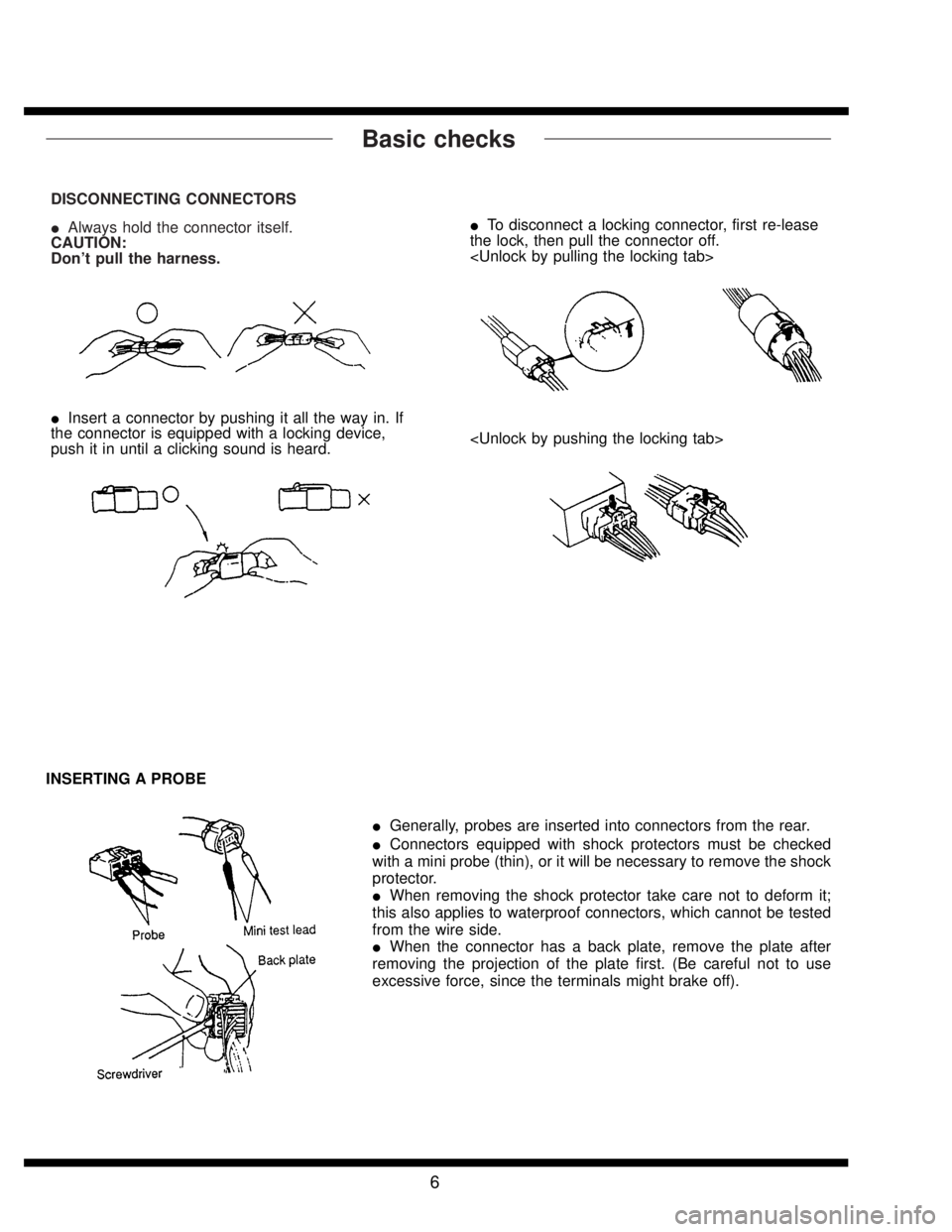
Basic checks
DISCONNECTING CONNECTORS
�Always hold the connector itself.
CAUTION:
Don’t pull the harness.
�To disconnect a locking connector, first re-lease
the lock, then pull the connector off.
�Insert a connector by pushing it all the way in. If
the connector is equipped with a locking device,
push it in until a clicking sound is heard.
INSERTING A PROBE
�Generally, probes are inserted into connectors from the rear.
�Connectors equipped with shock protectors must be checked
with a mini probe (thin), or it will be necessary to remove the shock
protector.
�When removing the shock protector take care not to deform it;
this also applies to waterproof connectors, which cannot be tested
from the wire side.
�When the connector has a back plate, remove the plate after
removing the projection of the plate first. (Be careful not to use
excessive force, since the terminals might brake off).
6

R4 1 Black B-2 Parking brake switch
R5 2 * B-2 Select lever illumination light
R6 2 Black B-2 Shif")