Page 2713 of 2890

8. Diagnostics Chart with Trouble Code
A: TROUBLE CODE
Trouble code Item Contents of diagnosis Page
10 OK Normal 18
11 BRAKE/ST/CL or N�Input signals from brake switch“OFF”, stop light
switch“ON”(Brake pedal is in depressed condi-
tion.)
�Input signals from clutch switch“OFF”, or inhibi-
tor switch is in“N”position.
[Clutch pedal is depressed (MT), or select lever
is set to N position (AT).]20
12 NOT SET SP Out of cruise speed range 22
13 LOW SP LIM Low-speed control limiter 22
14 CANCEL SW Input signal from cancel switch 26
15 NO MEMORY No memorized cruise speed—
21 SP SENS NG Faulty vehicle speed sensor 2 22
22 COM SW NGFaulty SET/COAST switch or RESUME/ACCEL
switch26
23 RELAY NG Faulty safety relay included in cruise control module 29
24 CPU RAM NG Faulty CPU RAM included in cruise control module 29
31 MOTOR NG Faulty vacuum motor or motor drive system 30
32 AIR VAL NG Faulty air valve or valve drive system 30
33 REL VAL NG Faulty release valve or valve drive system 30
16
6-2BODY ELECTRICAL SYSTEM
8. Diagnostics Chart with Trouble Code
Page 2715 of 2890
BR
5 Inhibitor switch (AT) N
6——
7——
8——
9——
10—�")
LED No. Signal name Display
1 SET/COAST switch SE
2 RESUME/ACCEL switch RE
3 Stop light switch ST
4�Brake switch
�Clutch switch (MT)BR
5 Inhibitor switch (AT) N
6——
7——
8——
9——
10——
SE RE ST BR N
—————
1
2345
678910
1. CHECK THE SIGNAL USING A SELECT MONITOR.
1) Turn ignition switch to ON.
2) Turn cruise control main switch to ON.
3) Set select monitor in“FA 0”mode.
4) Check signals for proper operation.
(1) When pushing the SET switch:
LED No. 1 goes out—lights.
(2) When pushing the RESUME switch:
LED No. 2 goes out—lights.
B6M0533
B6M0527
2. CHECK THE CRUISE CONTROL COMMAND
SWITCH.
1) Disconnect connector from command switch.
2) Measure voltage between connector (S1) and body.
Connector & terminal / Specified voltage:
(S1) No. 1—Body / 10 V, or more
3) Check for harness short circuit between command
switch and body.
Terminals / Specified resistance:
No. 2—Body / 1 MΩ, min.
No. 3—Body / 1 MΩ, min.
B6M0534
4) Measure resistance between each terminal of switch
side connector to check the switch operation.
Terminals:
No. 1—No. 2 (SET/COAST SWITCH)
No. 1—No. 3 (RESUME/ACCEL SWITCH)
Specified resistance:
10Ω, max. (ON)
1MΩ, min. (OFF)
18
6-2BODY ELECTRICAL SYSTEM
8. Diagnostics Chart with Trouble Code
Page 2716 of 2890
B6M0244
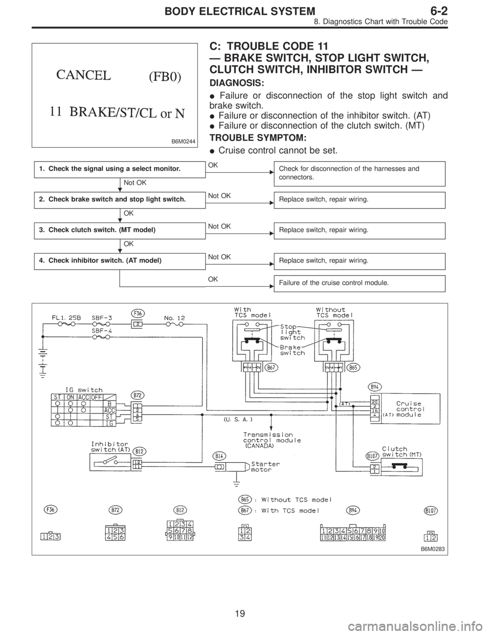
C: TROUBLE CODE 11
—BRAKE SWITCH, STOP LIGHT SWITCH,
CLUTCH SWITCH, INHIBITOR SWITCH—
DIAGNOSIS:
�Failure or disconnection of the stop light switch and
brake switch.
�Failure or disconnection of the inhibitor switch. (AT)
�Failure or disconnection of the clutch switch. (MT)
TROUBLE SYMPTOM:
�Cruise control cannot be set.
1. Check the signal using a select monitor.
Not OK
�OK
Check for disconnection of the harnesses and
connectors.
2. Check brake switch and stop light switch.
OK
�Not OK
Replace switch, repair wiring.
3. Check clutch switch. (MT model)
OK
�Not OK
Replace switch, repair wiring.
4. Check inhibitor switch. (AT model)�Not OK
Replace switch, repair wiring.
�OK
Failure of the cruise control module.
B6M0283
�
�
�
19
6-2BODY ELECTRICAL SYSTEM
8. Diagnostics Chart with Trouble Code
Page 2717 of 2890
BR
5 Inhibitor switch (AT) N
6——
7——
8——
9——
10—�")
LED No. Signal name Display
1 SET/COAST switch SE
2 RESUME/ACCEL switch RE
3 Stop light switch ST
4�Brake switch
�Clutch switch (MT)BR
5 Inhibitor switch (AT) N
6——
7——
8——
9——
10——
SE RE ST BR N
—————
1
2345
678910
1. CHECK THE SIGNAL USING A SELECT MONITOR.
1) Turn ignition switch to ON.
2) Turn cruise control main switch to ON.
3) Apply parking brake securely.
4) Set select monitor in“FA 0”mode.
5) Release the clutch pedal. (MT model)
6) Depress the brake pedal and check signals for proper
operation.
Stop light switch: LED No. 3 goes out—lights.
Brake switch : LED No. 4 goes out—lights.
7) Release the brake pedal.
8) Depress the clutch pedal and check signal for proper
operation. (MT model)
Clutch switch: LED No. 4 goes out—lights.
9) Set the selector lever from D to N position and check
signal for proper operation. (AT model)
Inhibitor switch: LED No. 5 goes out—lights.
G6M0183
2. CHECK BRAKE SWITCH AND STOP LIGHT
SWITCH.
1) Remove connector of stop and brake switch.
2) Check circuit between each terminal.
Pedal operationBrake switch between
No. 1—No. 4Stop light switch between
No. 2—No. 3
Depressing the
brake pedal.1MΩ,ormore 1Ω, or less
Without
depressing the
brake pedal.1Ω, or less 1 MΩ,ormore
G6M0184
3. CHECK CLUTCH SWITCH. (MT MODEL)
1) Disconnect connector from clutch switch.
2) Check continuity of the clutch switch.
Terminals / Specified resistance:
No. 1—No. 2 / 10Ω, max. (Without pedal
depressing.)
/1MΩ, min. (Pedal depressing.)
20
6-2BODY ELECTRICAL SYSTEM
8. Diagnostics Chart with Trouble Code
Page 2731 of 2890
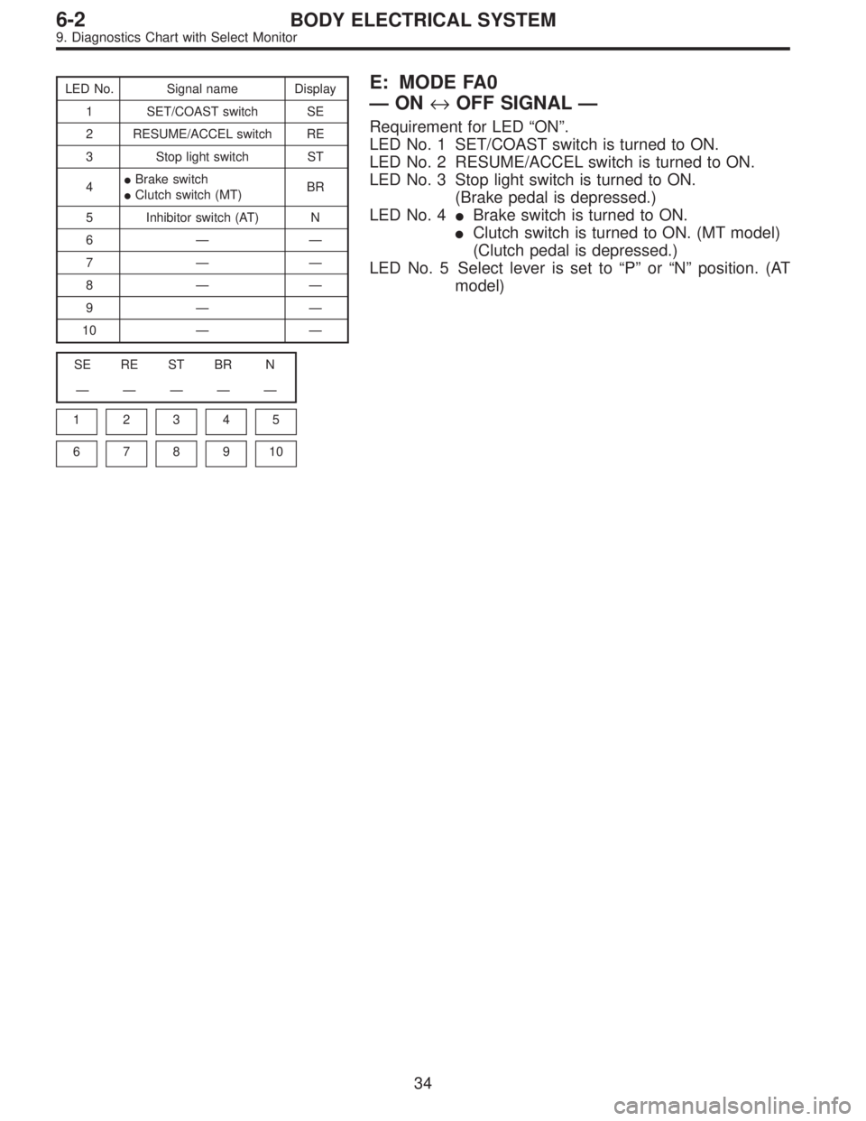
LED No. Signal name Display
1 SET/COAST switch SE
2 RESUME/ACCEL switch RE
3 Stop light switch ST
4�Brake switch
�Clutch switch (MT)BR
5 Inhibitor switch (AT) N
6——
7——
8——
9——
10——
SE RE ST BR N
—————
1
2345
678910
E: MODE FA0
—ON↔OFF SIGNAL—
Requirement for LED“ON”.
LED No. 1 SET/COAST switch is turned to ON.
LED No. 2 RESUME/ACCEL switch is turned to ON.
LED No. 3 Stop light switch is turned to ON.
(Brake pedal is depressed.)
LED No. 4�Brake switch is turned to ON.
�Clutch switch is turned to ON. (MT model)
(Clutch pedal is depressed.)
LED No. 5 Select lever is set to“P”or“N”position. (AT
model)
34
6-2BODY ELECTRICAL SYSTEM
9. Diagnostics Chart with Select Monitor
Page 2741 of 2890
 When working under a vehicle which is jacked-up,
always be sure to use safety stands.
2) The parking brake m")
3. Working Precautions
1. PRECAUTIONS WHEN WORKING WITH THE
PARTS MOUNTED ON THE VEHICLE
1) When working under a vehicle which is jacked-up,
always be sure to use safety stands.
2) The parking brake must always be applied during work-
ing. Also, in automatic transmission vehicles, keep the
select lever set to the P (Parking) range.
3) Be sure the workshop is properly ventilated when run-
ning the engine. Further, be careful not to touch the belt or
fan while the engine is operating.
4) Be careful not to touch hot metal parts, especially the
radiator and exhaust system immediately after the engine
has been shut off.
2. PRECAUTIONS IN TROUBLE DIAGNOSIS AND
REPAIR OF ELECTRIC PARTS
1) The battery cable must be disconnected from the bat-
tery’s (�) terminal, and the ignition switch must be set to the
OFF position, unless otherwise required by the diagnos-
tics.
2) Securely fasten the wiring harness with clamps and
slips so that the harness does not interfere with the body
end parts or edges and bolts or screws.
3) When installing parts, be careful not to catch them on
the wiring harness.
G6M0212
4) When disconnecting a connector, do not pull the wires,
but pull while holding the connector body.
11
6-3WIRING DIAGRAM
3. Working Precautions
Page 2747 of 2890
ABBREVIATION LIST
Abbr. Full name
A.B.S. Antilock Brake System
ACC Accessory
A/C Air Conditioning
AD Auto Down
AT Automatic Transmission
AU Auto Up
+B Battery
DN Down
DRL Daytime Running Light
E Ground
F/B Fuse & Joint Box
FL1.5 Fusible link 1.5 mm
2
IG Ignition
Illumi. Illumination
Abbr. Full name
LH Left Hand
Lo Low
M Motor
M/B Main Fuse Box
MG Magnet
Mi Middle
OP Optional Parts
PASS Passing
RH Right Hand
SBF Slow Blow Fuse
S.M.J. Super Multiple Junction
ST Starter
SW Switch
T.C.S. Traction Control System
UP Up
WASH Washer
17
6-3WIRING DIAGRAM
5. How to Use Super Multiple Junction (S.M.J.)
Page 2751 of 2890
No. Load
FB-24 Airbag control module
FB-25 Lighting switch
FB-26 Parking switch
FB-27 Parking switch
FB-28 Illumination light
FB-29 Illumination light
FB-30Pedal stroke switch
Stop light switch
Stop & brake switch
FB-31 Horn relay
FB-32 Blower motor relay
FB-33 Parking switch
FB-34License plate light
Rear combination light LH
Rear combination light RH
Rear finisher light LH
Rear finisher light RH
FB-35ABS control module
ABS/TCS control module
TCS valve relay
Cruise control main switch
Cruise control module
FB-36 Front fog light relay
21
6-3WIRING DIAGRAM
6. Wiring Diagram