Page 1300 of 2890
B4M0622A
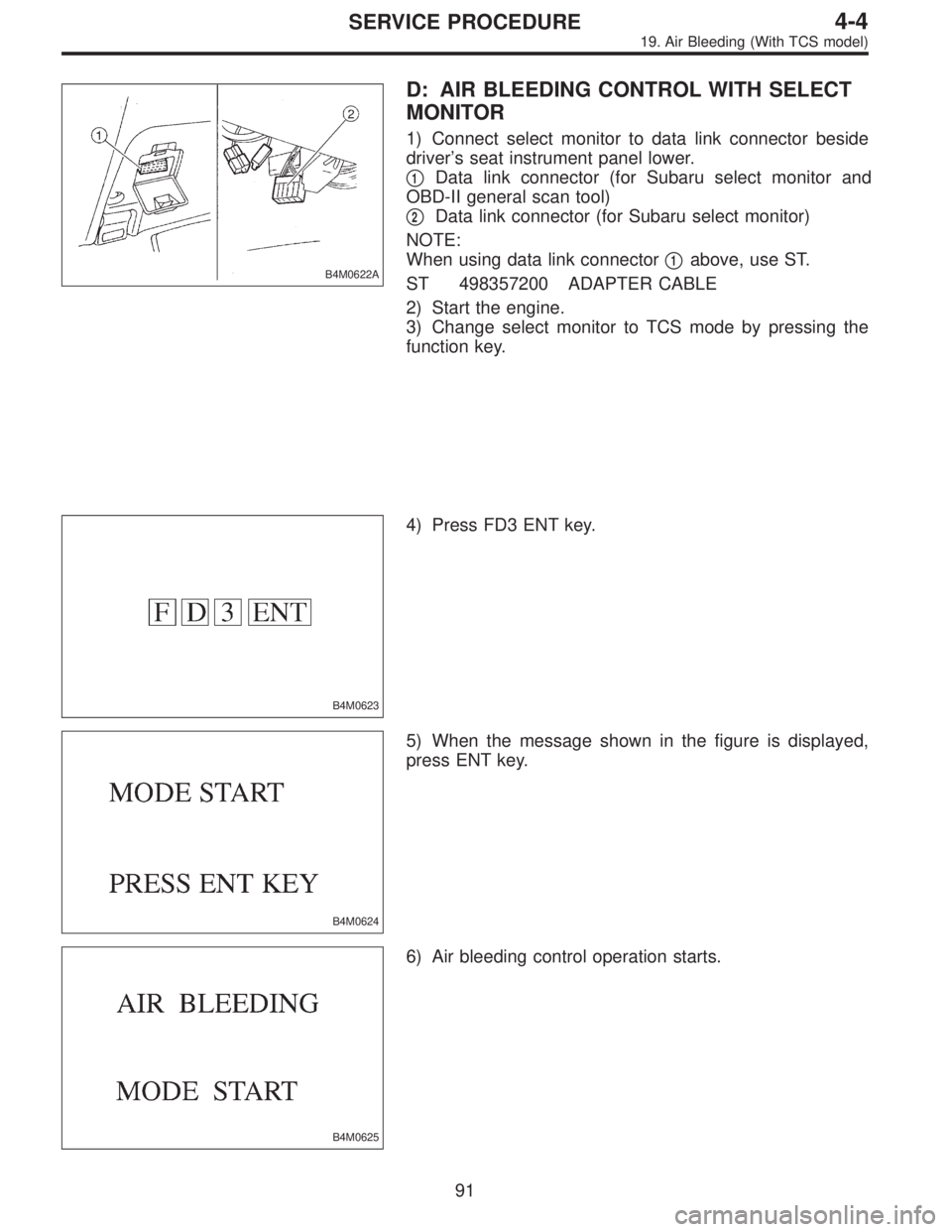
D: AIR BLEEDING CONTROL WITH SELECT
MONITOR
1) Connect select monitor to data link connector beside
driver’s seat instrument panel lower.
�
1Data link connector (for Subaru select monitor and
OBD-II general scan tool)
�
2Data link connector (for Subaru select monitor)
NOTE:
When using data link connector�
1above, use ST.
ST 498357200 ADAPTER CABLE
2) Start the engine.
3) Change select monitor to TCS mode by pressing the
function key.
B4M0623
4) Press FD3 ENT key.
B4M0624
5) When the message shown in the figure is displayed,
press ENT key.
B4M0625
6) Air bleeding control operation starts.
91
4-4SERVICE PROCEDURE
19. Air Bleeding (With TCS model)
Page 1307 of 2890
B4M0635
4) Press FD1 ENT key.
B4M0634
5) The message shown in the figure is displayed as fol-
lows:
(1) When using the brake tester, depress brake pedal
with braking force of 981 to 1,471 N (100 to 150 kg, 221
to 331 lb).
(2) When using the pressure gauge, depress brake
pedal so as to make the pressure gauge indicate 3,432
kPa (35 kg/cm
2, 498 psi)
B4M0624
6) When the message shown in the figure is displayed,
press ENT key.
7) Checked portions will be displayed on select monitor.
B4M0627
8) When ABS sequence control cannot be started (by sys-
tem malfunction, etc.), the message shown in the figure will
be displayed.
NOTE:
Read the trouble codes. Repair faulty parts.
9) After completion of ABS sequence control, turn ignition
switch OFF.
98
4-4SERVICE PROCEDURE
20. Hydraulic Unit for ABS/TCS System
Page 1309 of 2890
4. CONDITIONS FOR ABS SEQUENCE CONTROL
B4M0637A
NOTE:
When select monitor is used, control operation starts at
point A. It is not required to operate brake lamp switch for
starting ABS sequence control operation. The patterns
from IGN key ON to the point A show that operation is
started by diagnosis connector.
100
4-4SERVICE PROCEDURE
20. Hydraulic Unit for ABS/TCS System
Page 1313 of 2890
2. OPERATIONAL GUIDELINES OF THE TCS
SEQUENCE CONTROL WITH SELECT MONITOR
1) Connect select monitor to data link connector beside
driver’s seat heater unit.
2) Engine starts.
3) Put select monitor to TCS mode.
4) Put select monitor to FBI mode. Make sure code 11 is
indicated.
NOTE:
When trouble codes are stored in memory, repair the faulty
parts.
B4M0639
5) Press FD2 ENT key.
B4M0624
6) When the message shown in the figure is displayed,
press ENT key.
7) Checked portions will be displayed on select monitor.
B4M0627
8) When TCS sequence control cannot be started (by sys-
tem malfunction, etc.), the message shown in the figure will
be displayed.
NOTE:
Read the trouble codes. Repair faulty parts.
104
4-4SERVICE PROCEDURE
20. Hydraulic Unit for ABS/TCS System
Page 1315 of 2890
4. CONDITIONS FOR TCS SEQUENCE CONTROL
B4M0642A
NOTE:
When select monitor is used, control operation starts at
point A. It is not required to operate TCS OFF switch for
starting control operation. The patterns from IGN key ON
to point A show operation is started by diagnosis connec-
tor.
106
4-4SERVICE PROCEDURE
20. Hydraulic Unit for ABS/TCS System
Page 1324 of 2890
 Under the ABS sequence control, after the hydraulic
unit solenoid valve is driven, the operation of the hydraulic
unit can be checked by means of the brake tester or pres-
s")
D: ABS SEQUENCE CONTROL
1) Under the ABS sequence control, after the hydraulic
unit solenoid valve is driven, the operation of the hydraulic
unit can be checked by means of the brake tester or pres-
sure gauge.
2) ABS sequence control can be started by diagnosis con-
nector or select monitor.
B4M0082D
1. OPERATIONAL GUIDELINES OF THE ABS
SEQUENCE CONTROL WITH DIAGNOSIS
CONNECTOR
1) Connect diagnosis terminals to terminals No. 3 and No.
6 of the diagnosis connector beside driver’s seat heater
unit.
2) Set the speed of all wheels at 4 km/h (2 MPH) or less.
3) Turn ignition switch OFF.
4) Within 0.5 seconds after the ABS warning light goes
out, depress the brake pedal and hold it immediately after
ignition switch is turned to ON.
CAUTION:
Do not depress the clutch pedal.
NOTE:
�When the ignition switch is set to on, the brake pedal
must not be depressed.
�Engine must not operate.
5) After completion of ABS sequence control, turn ignition
switch OFF.
2. OPERATIONAL GUIDELINES OF THE ABS
SEQUENCE CONTROL WITH SELECT MONITOR
1) Connect select monitor to data link connector beside
driver’s seat heater unit.
2) Turn ignition switch ON.
3) Put select monitor to ABS mode.
B4M0635
4) PressFD1ENTkey.
11 4
4-4SERVICE PROCEDURE
22. Hydraulic Unit for ABS System (ABS 5.3 Type)
Page 1325 of 2890
B4M0997
5) The message shown in the figure is displayed.
B4M0998
6) The message shown in the figure is displayed as fol-
lows:
(1) When using the brake tester, depress brake pedal
with braking force of 981 N (100 kg, 221 lb).
(2) When using the pressure gauge, depress brake
pedal so as to make the pressure gauge indicate 3,432
kPa (35 kg/cm
2, 498 psi).
CAUTION:
Do not depress the clutch pedal.
B4M0999
7) When the message shown in the figure is displayed,
press ENT key.
8) Check points will be displayed on select monitor.
B4M1000
9) When ABS sequence control cannot be started (by sys-
tem malfunction, etc.), the message shown in the figure will
be displayed.
NOTE:
Read the trouble codes. Repair faulty parts.
B4M1030
10) After completion of ABS sequence control, turn ignition
switch OFF.
11 5
4-4SERVICE PROCEDURE
22. Hydraulic Unit for ABS System (ABS 5.3 Type)
Page 1326 of 2890
3. CONDITIONS FOR COMPLETION OF ABS
SEQUENCE CONTROL
When the following conditions develop, the ABS sequence
control stops and ABS operation is returned to the normal
control mode.
1) When the speed of at least one wheel reaches 10 km/h
(6 MPH).
2) When terminal No. 3 or No. 6 are separated from diag-
nosis terminals. (When select monitor is not used.)
3) When the brake pedal is released during sequence con-
trol and the braking lamp switch is set to off.
4) When brake pedal is depressed after ignition key is
turned to ON, and before ABS warning light goes out.
(When select monitor is not used.)
5) When brake pedal is not depressed after ignition key is
turned to ON, and within 0.5 seconds after ABS warning
light goes out. (When select monitor is not used.)
6) After completion of the sequence control.
7) When malfunction is detected. (When select monitor is
used.)
11 6
4-4SERVICE PROCEDURE
22. Hydraulic Unit for ABS System (ABS 5.3 Type)
 Press FD1 ENT key.
B4M0634
5) The message shown in the figure is displayed as fol-
lows:
(1) When using the brake tester, depress brake pedal
with braking force of 981 to 1,471 N (100 to 15")

![SUBARU LEGACY 1996 Service Repair Manual 2. OPERATIONAL GUIDELINES OF THE TCS
SEQUENCE CONTROL WITH SELECT MONITOR
1) Connect select monitor to data link connector beside
driver’s seat heater unit. <Ref. to [W19D0] step 1).>
2) Engine star](/manual-img/17/57433/w960_57433-1312.png "SUBARU LEGACY 1996 Service Repair Manual 2. OPERATIONAL GUIDELINES OF THE TCS
SEQUENCE CONTROL WITH SELECT MONITOR
1) Connect select monitor to data link connector beside
driver’s seat heater unit. <Ref. to [W19D0] step 1).>
2) Engine star")

 The message shown in the figure is displayed.
B4M0998
6) The message shown in the figure is displayed as fol-
lows:
(1) When using the brake tester, depress brake pedal
with braking force o")
 When the speed o")