Page 357 of 2890
B2M0386A
(3) Install valve spring and retainer.
CAUTION:
Be sure to install the valve springs with their close-
coiled end facing the seat on the cylinder head.
(4) Set ST on valve spring.
ST 499718000 VALVE SPRING REMOVER
(5) Compress valve spring and fit valve spring retainer
key.
(6) After installing, tap valve spring retainers lightly
with wooden hammer for better seating.
3) Install camshaft and support.
4) Install valve rocker assembly.
5) Install rocker cover.
47
2-3SERVICE PROCEDURE
6. Cylinder Head
Page 396 of 2890
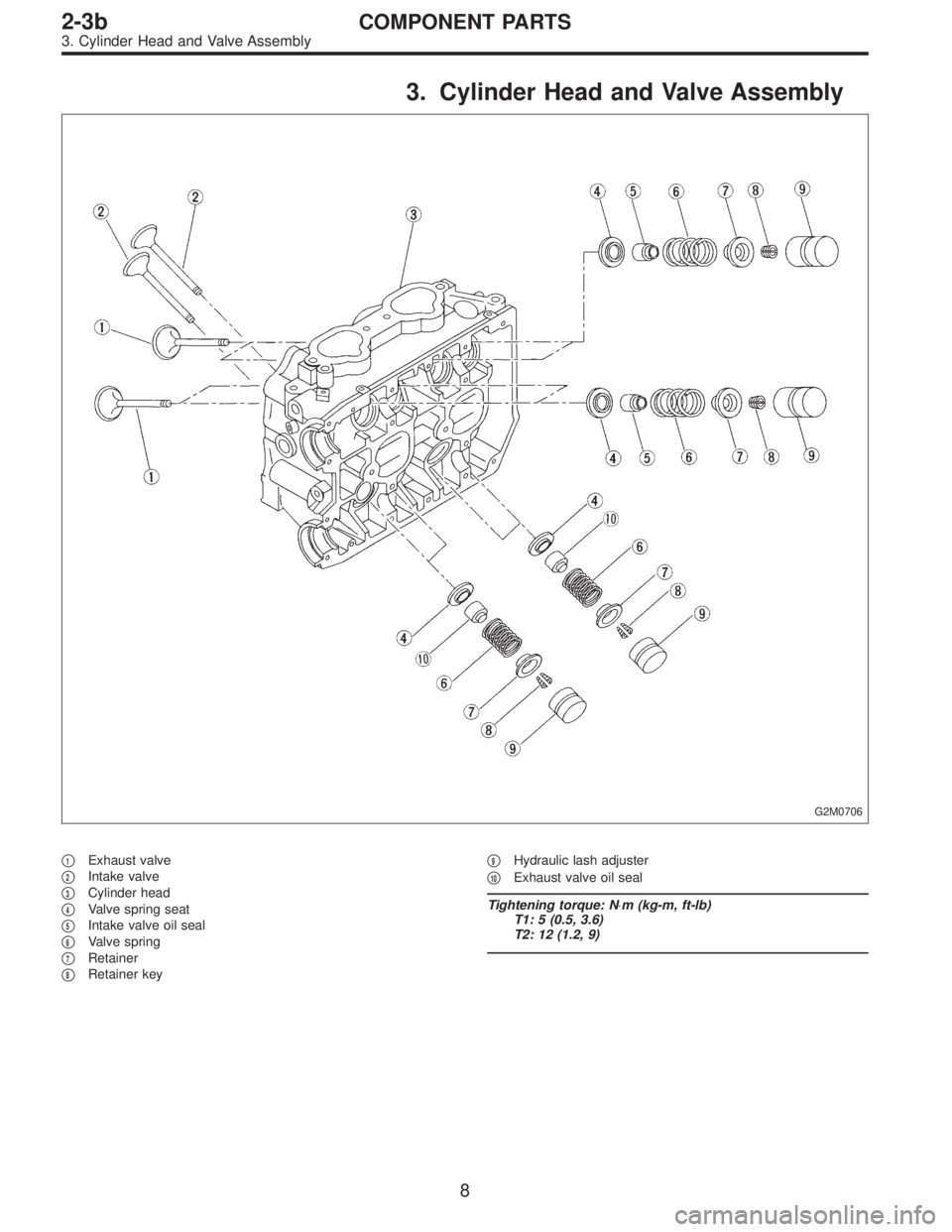
3. Cylinder Head and Valve Assembly
G2M0706
�1Exhaust valve
�
2Intake valve
�
3Cylinder head
�
4Valve spring seat
�
5Intake valve oil seal
�
6Valve spring
�
7Retainer
�
8Retainer key�
9Hydraulic lash adjuster
�
10Exhaust valve oil seal
Tightening torque: N⋅m (kg-m, ft-lb)
T1: 5 (0.5, 3.6)
T2: 12 (1.2, 9)
8
2-3bCOMPONENT PARTS
3. Cylinder Head and Valve Assembly
Page 398 of 2890
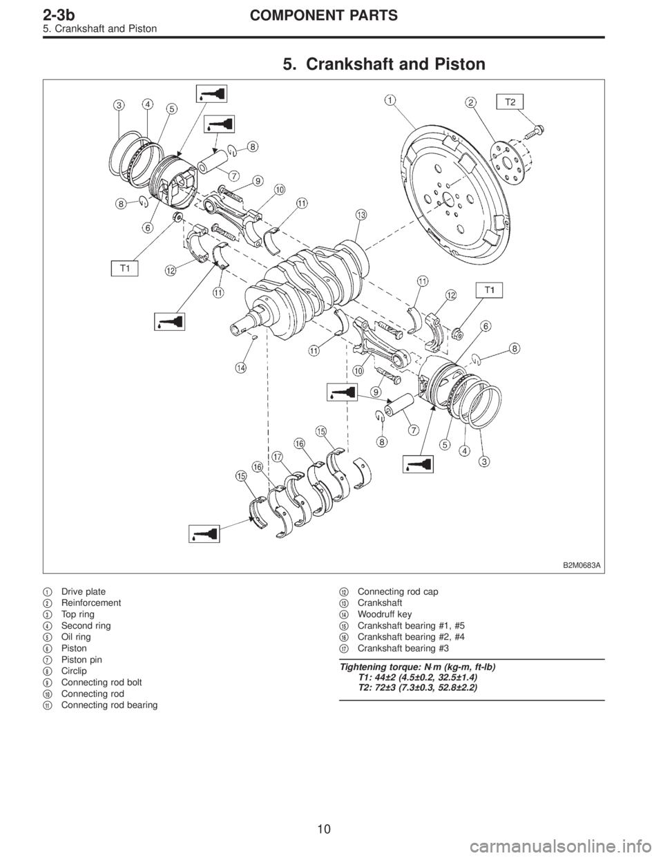
5. Crankshaft and Piston
B2M0683A
�1Drive plate
�
2Reinforcement
�
3Top ring
�
4Second ring
�
5Oil ring
�
6Piston
�
7Piston pin
�
8Circlip
�
9Connecting rod bolt
�
10Connecting rod
�
11Connecting rod bearing�
12Connecting rod cap
�
13Crankshaft
�
14Woodruff key
�
15Crankshaft bearing #1, #5
�
16Crankshaft bearing #2, #4
�
17Crankshaft bearing #3
Tightening torque: N⋅m (kg-m, ft-lb)
T1: 44±2 (4.5±0.2, 32.5±1.4)
T2: 72±3 (7.3±0.3, 52.8±2.2)
10
2-3bCOMPONENT PARTS
5. Crankshaft and Piston
Page 408 of 2890
5. SPROCKET
1) Check sprocket teeth for abnormal wear and scratches.
2) Make sure there is no free play between sprocket and
key.
3) Check crankshaft sprocket notch for sensor for damage
and contamination of foreign matter.
C: INSTALLATION
1. SPROCKET
B2M0691B
Tightening torque: N⋅m (kg-m, ft-lb)
T1: 4.9±0.5 (0.5±0.05, 3.6±0.4)
T2: 25±2 (2.5±0.2, 18±1.4)
T3: 78±5 (8.0±0.5, 58±3.6)
B2M0738
1) Install right-hand belt cover No. 2.
20
2-3bSERVICE PROCEDURE
2. Timing Belt
Page 425 of 2890
 Remove hydraulic lash adjusters.
2) Compress the valve spring and remove the valve spring
retainer key. Remove each valve and valve spring.
ST1 498267600 CYLINDER HEAD TABLE
ST2 499718000 V")
G2M0759
1) Remove hydraulic lash adjusters.
2) Compress the valve spring and remove the valve spring
retainer key. Remove each valve and valve spring.
ST1 498267600 CYLINDER HEAD TABLE
ST2 499718000 VALVE SPRING REMOVER
CAUTION:
�Mark each valve to prevent confusion.
�Use extreme care not to damage the lips of the
intake valve oil seals and exhaust valve oil seals.
G2M0760
C: INSPECTION
1. CYLINDER HEAD
1) Make sure that no crack or other damage exists. In
addition to visual inspection, inspect important areas by
means of red check.
2) Measure the warping of the cylinder head surface that
mates with crankcase by using a straight edge and thick-
ness gauge.
If the warping exceeds 0.05 mm (0.0020 in), regrind the
surface with a surface grinder.
Warping limit:
0.05 mm (0.0020 in)
Grinding limit:
0.3 mm (0.012 in)
Standard height of cylinder head:
127.5 mm (5.02 in)
CAUTION:
Uneven torque for the cylinder head nuts can cause
warping. When reassembling, pay special attention to
the torque so as to tighten evenly.
37
2-3bSERVICE PROCEDURE
4. Cylinder Head
Page 430 of 2890
D: ASSEMBLY
G2M0768
G2M0759
1) Installation of valve spring and valve
(1) Coat stem of each valve with engine oil and insert
valve into valve guide.
CAUTION:
When inserting valve into valve guide, use special care
not to damage the oil seal lip.
(2) Set cylinder head on ST1.
(3) Install valve spring and retainer using ST2.
ST1 498267600 CYLINDER HEAD TABLE
ST2 499718000 VALVE SPRING REMOVER
CAUTION:
Be sure to install the valve springs with their close-
coiled end facing the seat on the cylinder head.
(4) Compress valve spring and fit valve spring retainer
key.
(5) After installing, tap valve spring retainers lightly
with wooden hammer for better seating.
2) Install hydraulic lash adjuster.
42
2-3bSERVICE PROCEDURE
4. Cylinder Head
Page 766 of 2890
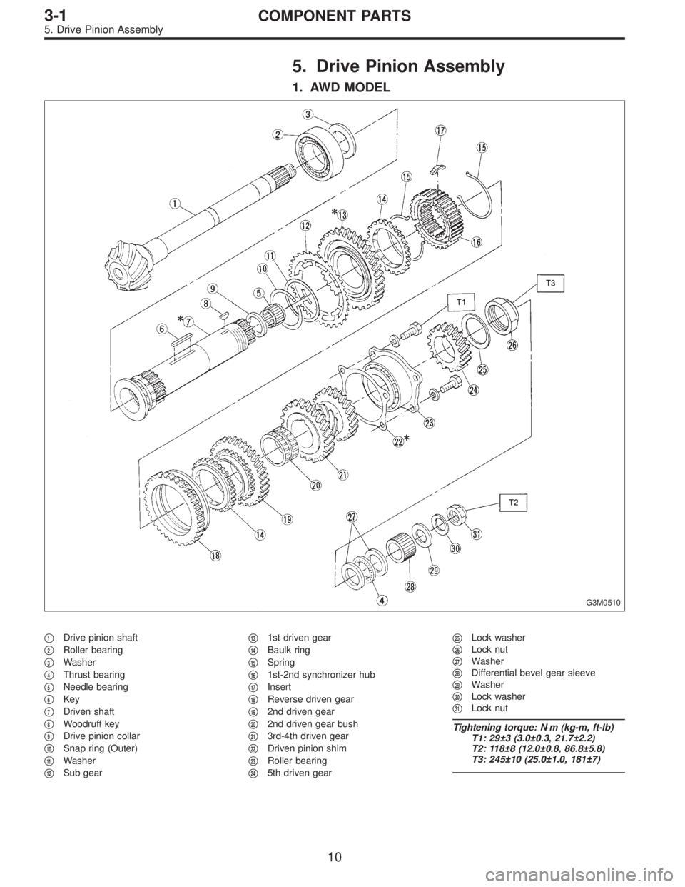
5. Drive Pinion Assembly
1. AWD MODEL
G3M0510
�1Drive pinion shaft
�
2Roller bearing
�
3Washer
�
4Thrust bearing
�
5Needle bearing
�
6Key
�
7Driven shaft
�
8Woodruff key
�
9Drive pinion collar
�
10Snap ring (Outer)
�
11Washer
�
12Sub gear�
131st driven gear
�
14Baulk ring
�
15Spring
�
161st-2nd synchronizer hub
�
17Insert
�
18Reverse driven gear
�
192nd driven gear
�
202nd driven gear bush
�
213rd-4th driven gear
�
22Driven pinion shim
�
23Roller bearing
�
245th driven gear�
25Lock washer
�
26Lock nut
�
27Washer
�
28Differential bevel gear sleeve
�
29Washer
�
30Lock washer
�
31Lock nut
Tightening torque: N⋅m (kg-m, ft-lb)
T1: 29±3 (3.0±0.3, 21.7±2.2)
T2: 118±8 (12.0±0.8, 86.8±5.8)
T3: 245±10 (25.0±1.0, 181±7)
10
3-1COMPONENT PARTS
5. Drive Pinion Assembly
Page 767 of 2890
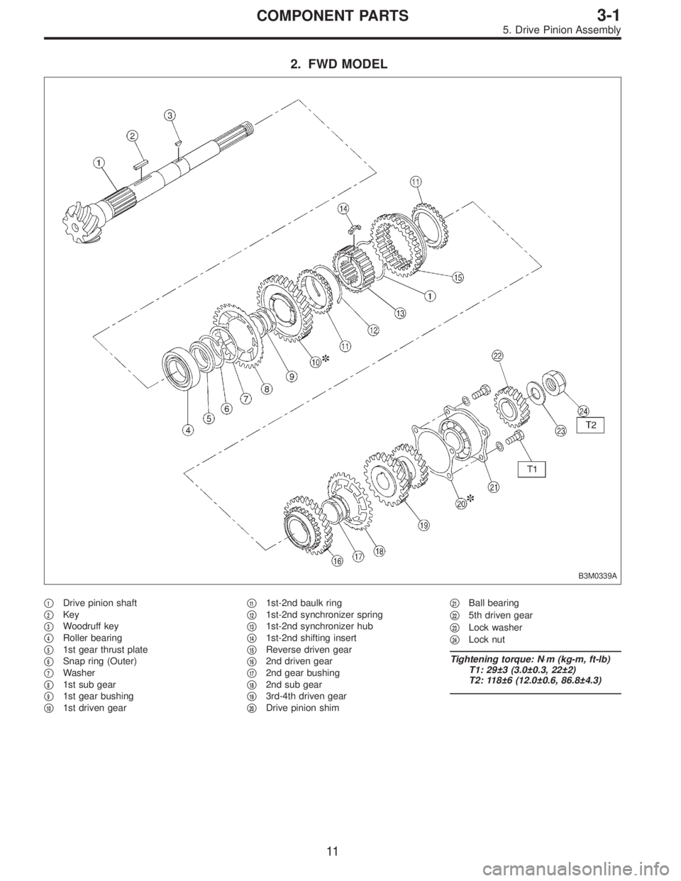
2. FWD MODEL
B3M0339A
�1Drive pinion shaft
�
2Key
�
3Woodruff key
�
4Roller bearing
�
51st gear thrust plate
�
6Snap ring (Outer)
�
7Washer
�
81st sub gear
�
91st gear bushing
�
101st driven gear�
111st-2nd baulk ring
�
121st-2nd synchronizer spring
�
131st-2nd synchronizer hub
�
141st-2nd shifting insert
�
15Reverse driven gear
�
162nd driven gear
�
172nd gear bushing
�
182nd sub gear
�
193rd-4th driven gear
�
20Drive pinion shim�
21Ball bearing
�
225th driven gear
�
23Lock washer
�
24Lock nut
Tightening torque: N⋅m (kg-m, ft-lb)
T1: 29±3 (3.0±0.3, 22±2)
T2: 118±6 (12.0±0.6, 86.8±4.3)
11
3-1COMPONENT PARTS
5. Drive Pinion Assembly
 Install valve spring and retainer.
CAUTION:
Be sure to install the valve springs with their close-
coiled end facing the seat on the cylinder head.
(4) Set ST on valve spring.
ST 49971800")
 Check sprocket teeth for abnormal wear and scratches.
2) Make sure there is no free play between sprocket and
key.
3) Check crankshaft sprocket notch for sensor for damage
and contamina")
 Installation of valve spring and valve
(1) Coat stem of each valve with engine oil and insert
valve into valve guide.
CAUTION:
When inserting valve into valve guide, use")