Page 241 of 2890

ON-BOARD
DIAGNOSTICS
II
SYSTEM
10
.
Diagnostics
Chart
with
Trouble
Code
Data
link
connector
(for
Subaru
select
monitor
and
OBD-II
general
scan
tool)
)
~
~A~
~
Data
link
connector
(f")
2-7
[T10BS1)
ON-BOARD
DIAGNOSTICS
II
SYSTEM
10
.
Diagnostics
Chart
with
Trouble
Code
Data
link
connector
(for
Subaru
select
monitor
and
OBD-II
general
scan
tool)
)
'
~
'~A~
~
Data
link
connector
(for
Subaru
select
monitor
only)
82M1016A]
TNKP
(F43)
0
.
10
k
P
a
1
mmHg
H2M
1326
TNKP
(F43)
0
.
10
k
P
a
1
mmHg
H2M1326
CONNECT
SUBARU
SELECT
MONITOR
OR
10BS1
THE
OBD-II
GENERALSCAN
TOOL,
AND
READ
DATA
.
1)
Turn
ignition
switch
to
OFF
.
2)
Remove
fuel
filler
cap
.
3)
Install
fuel
filler
cap
.
4)
Connect
Subaru
Select
Monitor
or
the
OBD-II
general
scan
toolto
data
link
connector
.
5)
Turn
ignition
switchto
ON
and
Subaru
Select
Monitor
or
the
OBD-II
general
scan
tool
switch
to
ON
.
6)
Read
the
data
onSubaru
Select
Monitoror
the
OBD-II
general
scan
tool
.
o
Subaru
Select
Monitor
Designate
mode
using
functionkey
.
Function
mode
:
F43
o
F43
:
Display
shows
pressure
signal
value
sent
from
fuel
tank
pressure
sensor
.
CHECK
:
Is
the
value
less
than-2
.8
kPa
in
function
mode
F43?
,rES
:
Go
to
step
10BS2
.
No
:
Go
to
next
CHECK
CHECK
:
Is
the
value
more
than2
.8
kPa
in
function
mode
F43?
,rES
:
Go
to
step
10BS4
.
No
:
Repair
harness
and
connector
.
NOTE
:
In
this
case,
repair
the
following
:
9
Open
or
short
circuit
in
harness
between
fuel
tank
p
sure
sensor
and
ECM
connector
"
Poor
contact
in
coupling
connector
(B97)
"
Poor
contact
in
fuel
tank
pressure
sensor
"
Poor
contact
in
ECM
connector
"
OBD-II
general
scan
tool
For
detailed
operation
procedures,
referto
the
OB
General
Scan
Tool
Instruction
Manual
.
30
res-
D-II
Page 242 of 2890
![SUBARU LEGACY 1996 Service Repair Manual
ON-BOARD
DIAGNOSTICS
II
SYSTEM
[TIossz]
2-7
10
.
Diagnostics
Chart
with
Trouble
Code
TNKP
(F43)
0
.
10
k
P
a
1
mmHg
H2M
1326
CHECK
INPUT
SIGNAL
FOR
ECM
.
(USING
10BS2
VOLTAGE
METER
AND
SUBARU
SEL](/manual-img/17/57433/w960_57433-241.png "SUBARU LEGACY 1996 Service Repair Manual
ON-BOARD
DIAGNOSTICS
II
SYSTEM
[TIossz]
2-7
10
.
Diagnostics
Chart
with
Trouble
Code
TNKP
(F43)
0
.
10
k
P
a
1
mmHg
H2M
1326
CHECK
INPUT
SIGNAL
FOR
ECM
.
(USING
10BS2
VOLTAGE
METER
AND
SUBARU
SEL")
ON-BOARD
DIAGNOSTICS
II
SYSTEM
[TIossz]
2-7
10
.
Diagnostics
Chart
with
Trouble
Code
TNKP
(F43)
0
.
10
k
P
a
1
mmHg
H2M
1326
CHECK
INPUT
SIGNAL
FOR
ECM
.
(USING
10BS2
VOLTAGE
METER
AND
SUBARU
SELECT
MONITOR
.)
1)
Measure
voltage
between
ECM
connector
and
chassis
ground
.
CHECK
;
Connector
&
terminal
(884)
No
.
21
(+)
-
Chassis
ground
(
)
:
Is
the
voltage
more
than4
.5
V?
YES
:
Go
to
nextstep
2)
.
No
:
Go
to
next
CHECK
CHECK
:
Does
the
voltage
change
more
than
4
.5
Vby
shaking
harness
and
connector
of
ECM
while
monitoring
the
value
with
voltage
meter?
0
:
Repairpoorcontact
in
ECM
connector
.
No
:
Replace
ECM
.
2)
Measure
voltage
between
ECM
and
chassis
ground
.
CHECK
:
Connector
&
terminal
(B84)
No
.
4
(+)
-
Chassis
ground
(
)
:
Is
the
voltage
less
than
0
.2
V?
,mss
:
Go
to
step
10BS3
.
No
:
Go
to
next
step
3)
.
3)
Read
data
onSubaru
Select
Monitor
.
9
Subaru
Select
Monitor
Designate
mode
using
function
key
.
Function
mode
:
F43
9
F43
:
Display
shows
pressure
signal
value
sent
from
fuel
tankpressure
sensor
.
31
Page 246 of 2890
ON-BOARD
DIAGNOSTICS
II
SYSTEM
[TloBSa1
2-7
10
.
DiagnosticsChart
with
Trouble
Code
TNKP
(F43)
0
.
10
k
P
a
1
mmHg
H2M1326
5)
Disconnect
connector
from
fuel
tank
pressure
sensor
.
6)
Remove
fuel
filler
cap
.
7)
Install
fuel
filler
cap
.
8)
Turn
ignition
switchto
ON
and
Subaru
Select
Monitor
or
theOBD-II
general
scan
tool
switch
to
ON
.
9)
Read
data
onSubaru
select
monitor
or
the
OBD-II
gen-
eral
scan
tool
.
e
Subaru
Select
Monitor
Designate
mode
using
function
key
.
Function
mode
:
F43
CHECK
:
Is
the
value
more
than2
.8
kPa
in
function
mode
F43?
,rES
:
Repair
short
circuit
in
harnessbetween
ECM
and
fuel
tank
pressure
sensor
connector
.
No
:
Replace
fuel
tankpressure
sensor
.
~
OBD-II
general
scan
tool
For
detailed
operation
procedures,
referto
the
OBD-II
General
Scan
Tool
Instruction
Manual
.
35
Page 259 of 2890
![SUBARU LEGACY 1996 Service Repair Manual
ON-BOARD
DIAGNOSTICS
II
SYSTEM
[r1oBwa]
2-7
10
.
Diagnostics
Chart
with
Trouble
Code
FLEVEL
(F45)
2
.50V
H2M1327
3
2
1
5
4
D
S2
B2M0935
I
CHECK
:
Does
the
value
change
less
than
0
.12
Vby
s](/manual-img/17/57433/w960_57433-258.png "SUBARU LEGACY 1996 Service Repair Manual
ON-BOARD
DIAGNOSTICS
II
SYSTEM
[r1oBwa]
2-7
10
.
Diagnostics
Chart
with
Trouble
Code
FLEVEL
(F45)
2
.50V
H2M1327
3
2
1
5
4
D
S2
B2M0935
I
CHECK
:
Does
the
value
change
less
than
0
.12
Vby
s")
ON-BOARD
DIAGNOSTICS
II
SYSTEM
[r1oBwa]
2-7
10
.
Diagnostics
Chart
with
Trouble
Code
FLEVEL
(F45)
2
.50V
H2M1327
3
2
1
5
4
D
S2
B2M0935
I
CHECK
:
Does
the
value
change
less
than
0
.12
Vby
shaking
harness
and
connector
of
ECM
while
monitoring
the
value
with
Subaru
Select
Monitor?
9
Subaru
Select
Monitor
Designate
mode
using
function
key
.
Function
mode
:
F45
9
F45
:
Fuel
level
sensor
output
signal
is
indicated
.
,rES
:
Repair
poor
contact
in
ECM
connector
.
No
:
Even
if
MIL
lights
up,
the
circuit
has
returned
to
a
normal
condition
at
this
time
.
A
temporary
poor
contact
of
the
connector
may
be
the
cause
.
NOTE
:
In
this
case,
repair
the
following
:
"
Poor
contact
in
fuel
pump
connector
"
Poor
contact
in
combination
meter
connector
"
Poor
contact
in
ECM
connector
"
Poor
contact
in
coupling
connector
(i3,
1322,
B97and
R57)
10BW4
CHECK
FUEL
LEVEL
SENSOR
.
1)
Turn
ignition
switch
to
OFF
.
2)
Remove
fuel
pump
access
hole
lid
located
on
the
right
rear
of
luggage
compartment
floor
.
3)
Disconnect
connector
from
fuel
pump
.
4)
Measure
resistance
between
connector
terminals
of
fuel
pump
.
CHECK
:
Terminals
No
.
3
-
No
.
5
:
Is
the
resistance
less
than
100
S2?
vES
:
Go
to
step
10BW5
.
No
:
Replace
fuel
sending
unit
.
49
Page 316 of 2890
3. Cylinder Head and Valve Assembly
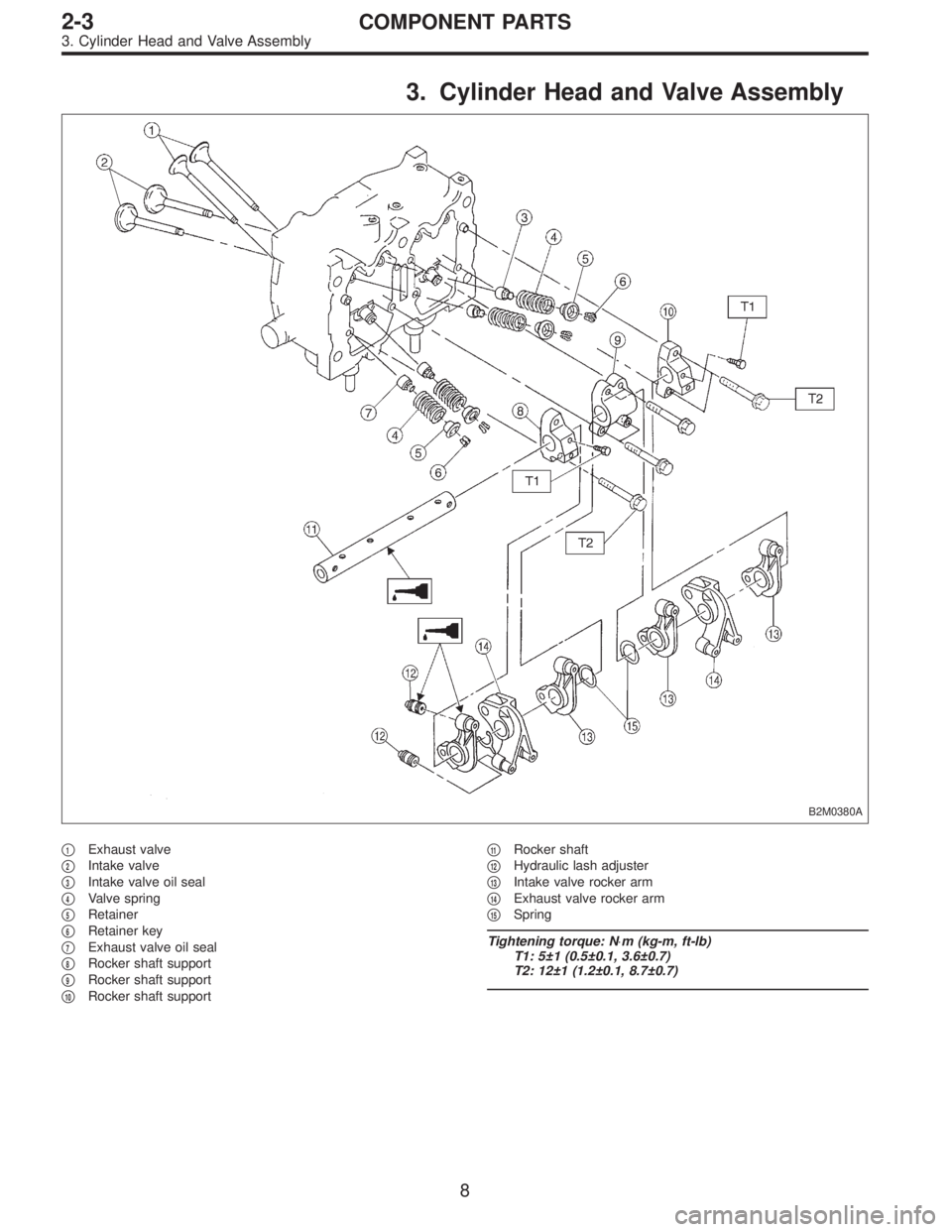
B2M0380A
�1Exhaust valve
�
2Intake valve
�
3Intake valve oil seal
�
4Valve spring
�
5Retainer
�
6Retainer key
�
7Exhaust valve oil seal
�
8Rocker shaft support
�
9Rocker shaft support
�
10Rocker shaft support�
11Rocker shaft
�
12Hydraulic lash adjuster
�
13Intake valve rocker arm
�
14Exhaust valve rocker arm
�
15Spring
Tightening torque: N⋅m (kg-m, ft-lb)
T1: 5±1 (0.5±0.1, 3.6±0.7)
T2: 12±1 (1.2±0.1, 8.7±0.7)
8
2-3COMPONENT PARTS
3. Cylinder Head and Valve Assembly
Page 318 of 2890
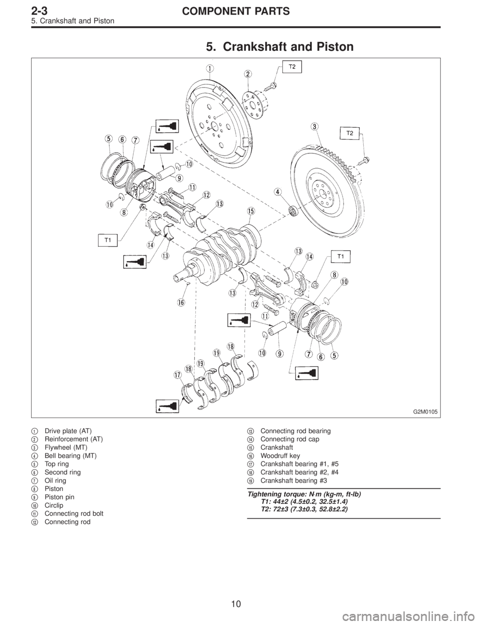
5. Crankshaft and Piston
G2M0105
�1Drive plate (AT)
�
2Reinforcement (AT)
�
3Flywheel (MT)
�
4Bell bearing (MT)
�
5Top ring
�
6Second ring
�
7Oil ring
�
8Piston
�
9Piston pin
�
10Circlip
�
11Connecting rod bolt
�
12Connecting rod�
13Connecting rod bearing
�
14Connecting rod cap
�
15Crankshaft
�
16Woodruff key
�
17Crankshaft bearing #1, #5
�
18Crankshaft bearing #2, #4
�
19Crankshaft bearing #3
Tightening torque: N⋅m (kg-m, ft-lb)
T1: 44±2 (4.5±0.2, 32.5±1.4)
T2: 72±3 (7.3±0.3, 52.8±2.2)
10
2-3COMPONENT PARTS
5. Crankshaft and Piston
Page 330 of 2890
B2M0108A
3) Measure the extension of rod beyond the body. If it is
not within specifications, replace with a new one.
Rod extension: H
15.4—16.4 mm (0.606—0.646 in)
3. BELT TENSIONER
1) Check mating surfaces of timing belt and contact point
of tension adjuster rod for abnormal wear or scratches.
Replace belt tensioner if faulty.
2) Check spacer and tensioner bushing for wear.
3) Check tensioner for smooth rotation. Replace if noise or
excessive play is noted.
4) Check tensioner for grease leakage.
4. BELT IDLER
1) Check idler for smooth rotation. Replace if noise or
excessive play is noted.
2) Check outer contacting surfaces of idler pulley for
abnormal wear and scratches.
3) Check idler for grease leakage.
5. SPROCKET
1) Check sprocket teeth for abnormal wear and scratches.
2) Make sure there is no free play between sprocket and
key.
3) Check crankshaft sprocket notch for sensor for damage
and contamination of foreign matter.
21
2-3SERVICE PROCEDURE
3. Timing Belt
Page 350 of 2890
B: DISASSEMBLY
B2M0121A
1) Remove rocker cover.
2) Remove valve rocker assembly.
3) Remove camshaft and support.
4) Place cylinder head on ST.
ST 498267200 CYLINDER HEAD TABLE
B2M0386A
5) Set ST on valve spring. Compress valve spring and
remove the valve spring retainer key. Remove each valve
and valve spring.
ST 499718000 VALVE SPRING REMOVER
CAUTION:
�Mark each valve to prevent confusion.
�Use extreme care not to damage the lips of the
intake valve oil seals and exhaust valve oil seals.
6) Removal of plug (cylinder head LH)
CAUTION:
Do not remove plug unless necessary.
40
2-3SERVICE PROCEDURE
6. Cylinder Head

0
.
10
k
P
a
1
mmHg
H2M1326
5)
Disconnect
connector
from
fuel
tank
pressure
sensor
.
6)
Remove
fuel")
 Measure the extension of rod beyond the body. If it is
not within specifications, replace with a new one.
Rod extension: H
15.4—16.4 mm (0.606—0.646 in)
3. BELT TENSIONER
1) Check mati")
![SUBARU LEGACY 1996 Service Repair Manual B: DISASSEMBLY
B2M0121A
1) Remove rocker cover.
2) Remove valve rocker assembly.
<Ref. to 2-3 [W4A0].>
3) Remove camshaft and support.
<Ref. to 2-3 [W5A0].>
4) Place cylinder head on ST.
ST 498267200](/manual-img/17/57433/w960_57433-349.png "SUBARU LEGACY 1996 Service Repair Manual B: DISASSEMBLY
B2M0121A
1) Remove rocker cover.
2) Remove valve rocker assembly.
<Ref. to 2-3 [W4A0].>
3) Remove camshaft and support.
<Ref. to 2-3 [W5A0].>
4) Place cylinder head on ST.
ST 498267200")