1996 SUBARU LEGACY key
[x] Cancel search: keyPage 175 of 2890
![SUBARU LEGACY 1996 Service Repair Manual
s-$
[D601]
WIRING
DIAGRAM
6
.
Wiring
Diagram
No
.
Load
MB-2
Powerwindow
circuit
breaker
Engine
control
module
Fuel
pump
relay
MB-3
Main
relay
OBD-II
service
connector
MB-4A/C
relay
holder
MB- SUBARU LEGACY 1996 Service Repair Manual
s-$
[D601]
WIRING
DIAGRAM
6
.
Wiring
Diagram
No
.
Load
MB-2
Powerwindow
circuit
breaker
Engine
control
module
Fuel
pump
relay
MB-3
Main
relay
OBD-II
service
connector
MB-4A/C
relay
holder
MB-](/manual-img/17/57433/w960_57433-174.png)
s-$
[D601]
WIRING
DIAGRAM
6
.
Wiring
Diagram
No
.
Load
MB-2
Powerwindow
circuit
breaker
Engine
control
module
Fuel
pump
relay
MB-3
Main
relay
OBD-II
service
connector
MB-4A/C
relay
holder
MB-6
Headlight
LH
Diode
(Lighting)
Lighting
switch
Combination
meter
M
B_$
Headlight
RH
Combination
meter
Door
lock
timer
MB-9
Luggage
room
light
Radio
Room
light
MB-10
A/C
relay
holder
ALT-1
Combination
meter
IG
A/C
relay
holder
Cruise
control
module
ST
Engine
control
module
Inhibitor
switch
FB-2
Diode
(A/C)
Sub
fan
motor
FB-3
Sub
fan
relay-2
Engine
control
module
Fuel
pump
relay
FB-4
Ignition
coil
Transmission
control
module
Side
marker
light
LH
FB-6
Side
marker
light
RH
FB-7Door
lock
timer
FB-9Hazard
switch
AT
shift
lock
control
module
FB-10
Key
warning
switch
Power
antenna
FB-11
Radio
FB-12
Cigarette
lighter
FB-13
Remote
control
rearview
mirrorswitch
AT
shift
lock
control
module
Combination
switch
Front
washer
motor
FB-14
Front
wipermotor
Rear
washer
motor
Rear
wipermotor
Rear
wiper
relay
FB-15Transmission
control
module
Na
Load
Rear
defogger
FB-16
Rear
defogger
condenser
Reardefogger
switch
FB-17
Rear
defogger
switch
FB-18
AT
shift
lock
control
module
Inhibitor
switch
FB-19
Hazard
switch
Combination
meter
FB-20
Mode
control
panel
FB-21
Combination
meter
(Airbag)
Blower
motor
relay
Check
connector
FB-22
FRESH/RECIRC
actuator
Mode
actuator
Powerwindow
relay
Seat
belt
timer
FB-23
Airbag
.
control
module
FB-24
Airbag
control
module
FB-25
Lighting
switch
FB-26
Parking
switch
FB-27
Parking
switch
FB-28
Illumination
light
FB-29
Illumination
light
FB-30
Stop
light
switch
Stop
&
brake
switch
FB-31
Horn
relay
FB-32
Blower
motor
relay
FB-33
Parking
switch
License
plate
light
LH
License
plate
light
RH
FB-34
Rear
combination
light
LH
Rear
combination
light
RH
Rear
finisher
light
LH
Rear
finisher
light
RH
FB-35
Cruise
control
main
switch
Cruise
control
module
Page 190 of 2890

r
Connecting
to
)r
Area
No
.
Name
C-4
D1
Front
doorcord
RH
ow
C-4
ABi
SRS
(Airbag)
harness
;k
C-4
Turn
&
hazard
module
.k
C-3
i1
C-3
i2
instrument
panel
wiring
un
C-3
i3
harness
e
C-3
i4
y
C-3
OBD-IIservice
connector
C-3
Power
window
circuit
breaker
C-3
Power
window
relay
;k
C-3
Illuminationcontrol
module
C-3
Seat
belt
timer
;n
B-4
Fuel
pump
relay
vn
B-4
Main
relay
;k
B-4
Horn
relay
B-4
Blower
relay
y
C-4
FIB
y
C-4
B-3
Shield
joint
connector
(AT)
.k
B-3
:k
B-3
Transmission
control
module
.k
B-3
:k
B-3
Shift-lock
control
module
B-4F44
i
h
B-4F45
Front
w
ring
arness
.k
B-3
Stop
light
switch
,k
B-3
Stop
8
brake
switch
(Withcruise
control)
:k
8-3
Cruise
control
sub
switch
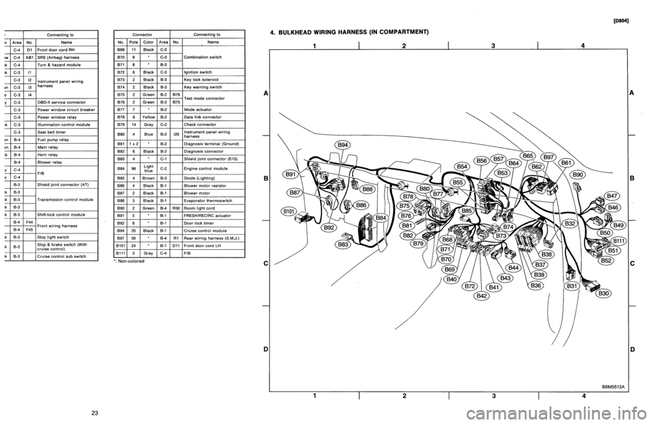
Connector
Connecting
to
No
.
Pole
Color
Area
No
.
Name
869
11
Black
C-3
B70
9
C-3
Combination
switch
B71
8
8-3
B72
6
Black
C-3
Ignition
switch
B73
2
Black
B-3
Key
lock
solenoid
B74
2
Black
B-3
Key
warning
switch
B75
2
Green
B-2
876
T
d
B76
2
Green
8-2
875
e
connector
est
mo
877
7
B-2
Mode
actuator
B78
9
Yellow
B-2
Data
link
connector
B79
14
Gray
C-2
Check
connector
BBO
4
Blue
B-2
i20
Instrument
panel
wiring
harness
B81
1
x
2
B-2
Diagnosis
terminal
(Ground)
B82
6
Black
B-2
Diagnosisconnector
BB3
4
C-1
Shield
joint
connector
(EIG)
BBQ
96Lightblue
C-2
Engine
control
module
B85
4
Brown
B-3
Diode
(Lighting)
B86
4
Black
B-1
Blower
motor
resistor
887
2
Black
B-1
Blower
motor
888
3
Black
B-1
Evaporatorthermoswitch
B90
2
Green
B-4
R50
Room
light
cord
B91
5
B-1
FRESHIRECIRC
actuator
B92
8
B-1
Door
lock
timer
894
20
Black
B-1
Cruise
control
module
B97
56
B-4
R1
Rear
wiring
harness
(S.M
.J
.)
B101
24
B-1
D11
Front
door
cord
LH
8111
3
Gray
C-4FIB
`
:
Non-colored
4
.
BULKHEAD
WIRING
HARNESS
(IN
COMPARTMENT)
1
I
2
I
3
I
4
A
B
C
D
1
I
2
I
3
I
4
[oeo41
B6M0513A
A
B
C
iJ
23
Page 191 of 2890

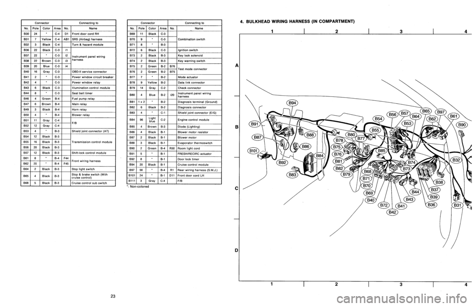
Connector
Connecting
to
No
.
Pole
Color
Area
No
.
Name
830
24
C-4
D1
Front
door
cord
RH
831
7
Yellow
C-4
A81
SRS
(Airbag)
harness
B32
3
Black
C-4
Turn
&
hazard
module
B36
22
Black
C-3
i1
B37
22
C-3
i2
Instrument
panel
wiring
B38
22
Brown
C-3
i3
harness
B39
20Blue
C-3
i4
B40
16
Gray
C-3
OBD-II
service
connector
B41
2
C-3
Power
window
circuit
breaker
842
4
C-3
Power
window
relay
B43
6
Black
C-3
Illumination
control
module
B44
8
C-3
Seat
belt
timer
B46
4
Green
B-4
Fuel
pump
relay
B47
6
Brown
B-4
Main
relay
B49
3
Black
B-4
Horn
relay
850
4
B-4
Blower
relay
851
11
Gray
C-4
FIB
B52
12
Gray
C-4
853
4
B-3
Shield
joint
connector
(AT)
B54
12
Black
B-3
B55
16
Black
B-3
Transmission
control
module
B56
20
Black
B-3
B57
12
Black
B-3
Shift-lock
control
module
861
B
B-4
F44
B62
20
B-4
F45
Front
wiring
harness
B64
2
Black
B-3
Stop
light
switch
B65
4
Black
B-3
Stop
&
brake
switch(Withcruise
control)
B68
5
i
Black
i
B-3
Cruise
control
sub
switch
Connector
Connecting
to
No
.
Pole
Color
Area
No
.
Name
B69
11
Black
C-3
B70
9
C-3
Combination
switch
B71
8
8-3
B72
6
Black
C-3
Ignition
switch
B73
2
Black
B-3
Key
lock
solenoid
B74
2
Black
B-3
Key
warning
switch
B75
2
Green
B-2
B76
B76
2
Green
&2
B75
Test
mode
connector
B77
7
B-2
Made
actuator
B78
9
Yellow
B-2
Data
link
connector
B79
14
Gray
C-2
Check
connector
B80
4
Blue
B-2
i20
Instrumentpanel
wiring
harness
B81
1
x
2
B-2
Diagnosis
terminal
(Ground)
B82
6
Black
B-2
Diagnosis
connector
B83
4
C-1
Shield
joint
connector
(E!G)
884
96
Light
blue
C-2
Engine
control
module
885
4
Brown
B-3
Diode
(Lighting)
B86
4
Black
B-1
Blower
motor
resistor
887
2
Black
B-1
Blower
motor
B88
3
Black
8-t
Evaporator
thermoswitch
890
2
Green
B-4
R50
Room
light
cord
B91
5B-1
FRESHIRECIRC
actuator
892
8
B-1
Door
lock
timer
B94
20
Black
B-1
Cruise
control
module
B97
56
B-4
R1Rear
wiring
harness
(S
.M
.J
.)
B101
24
B-1
D11
Front
doorcord
LH
13111
3
Gray
C-4
FIB
`
:
Non-colored
4
.
BULKHEAD
WIRING
HARNESS
(IN
COMPARTMENT)
A
B
C
1]
4
23
Page 195 of 2890
![SUBARU LEGACY 1996 Service Repair Manual
AUTOMATIC
TRANSMISSION
AND
DIFFERENTIAL
[T7H3]
3-2
7
.
Diagnostic
Chart
with
Trouble
Code
B54
123456
7
8
9
01112
D
L
.0
Q
0>
B3M02248
B54
161514
3
H87
1211
10
9
D
_E)VSj
83M0222B
Data
link SUBARU LEGACY 1996 Service Repair Manual
AUTOMATIC
TRANSMISSION
AND
DIFFERENTIAL
[T7H3]
3-2
7
.
Diagnostic
Chart
with
Trouble
Code
B54
123456
7
8
9
01112
D
L
.0
Q
0>
B3M02248
B54
161514
3
H87
1211
10
9
D
_E)VSj
83M0222B
Data
link](/manual-img/17/57433/w960_57433-194.png)
AUTOMATIC
TRANSMISSION
AND
DIFFERENTIAL
[T7H3]
3-2
7
.
Diagnostic
Chart
with
Trouble
Code
B54
123456
7
8
9
01112
D
L
.0
Q
0>
B3M02248
B54
161514
3
H87
1211
10
9
D
_E)VSj
83M0222B
Data
link
connector
(for
Subaru
select
monitor
and
OBD-II
general
scan
tool)
/
'
/
i
Data
link
connector
(for
Subaru
select
monitor
\
,only)
ls%y~
x~/
OBD0145A
I
AFM
(F15)
0
.6V
B3M0370
2
.
CHECK
HARNESS
CONNECTOR
BETWEEN
TCM
AND
ECM
.
1)
Turn
ignition
switch
to
OFF
.
2)
Disconnect
connectors
from
TCM
and
ECM
.
3)
Measure
resistance
of
harness
connector
between
TCM
and
ECM
.
Connector
&
terminal
I
Specifiedresistance
:
(B54)
No
.
9
-
(B84)
No
.
47
l
1
S2,
orless
4)
Measure
resistance
of
harness
connector
between
TCM
and
body
to
make
sure
that
circuit
does
not
short
.
Connector
&
terminal
/
Specified
resistance
:
(854)
No
.
9
-
Body
11
MSZ,
or
more
3
.
CHECK
INPUT
SIGNAL
FOR
TCM
.
1)
Connect
connectors
to
TCM
and
ECM
.
2)
Start
the
engine
.
(engine
idling
after
warm-up)
3)
Measure
signal
voltage
between
TCM
connector
termi-
nal
and
body
.
Connector
&
terminal
/
Specified
voltage
:
Engine
warm-up
;
(B54)
No
.
9
-
Body
l
0
.5
-
1
.22
V
9
Using
Subaru
select
monitor
:
(1)
Connect
connectors
to
TCM
and
ECM
.
(2)
Turn
ignition
switch
to
OFF
.
(3)
Connect
the
Subaru
select
monitor
to
data
link
connector
.
(4)
Turn
ignition
switch
to
ON
and
Subaru
select
monitor
switch
to
ON
.
(5)
Start
andwarm-up
the
engine
.
(6)
Read
data
onSubaru
select
monitor
.
(7)
Designate
mode
using
function
key
.
Function
mode
:
F15
SPECIFIED
DATA
:
0
.5
-
1
.22
V
(Engine
warm-up)
5
Page 197 of 2890

AUTOMATIC
TRANSMISSION
AND
DIFFERENTIAL
[T7i21
3-2
7
.
Diagnostic
Chart
with
Trouble
Code
OBD0410A
I
Data
link
connector
(for
Subaru
select
monitor
and
OBD-II
general
scan
tool)
/'
/
/
i
~1
i
Data
link
connector
(for
Subaru
select
monitor
\
only)
lqo~
,
/"~///
OBD0145A
I
EREV
(F06)
1,500
rpm
G3M0727
1
.
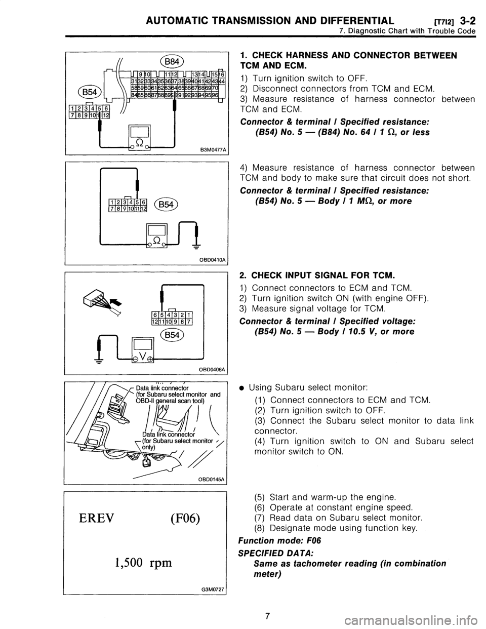
CHECK
HARNESS
AND
CONNECTOR
BETWEEN
TCMAND
ECM
.
1)
Turn
ignition
switch
to
OFF
.
2)
Disconnect
connectors
from
TCM
and
ECM
.
3)
Measure
resistance
of
harness
connector
between
TCM
and
ECM
.
Connector
&
terminal
l
Specified
resistance
:
(854)
No
.
5
-
(B84)
No
.
64
I1
S2,
or
less
4)
Measure
resistance
of
harness
connector
between
TCM
and
body
to
make
sure
that
circuit
does
not
short
.
Connector
&
terminal
l
Specifiedresistance
:
(B54)
No
.
5
-
Body
I
1
MSS,or
more
2
.
CHECK
INPUT
SIGNAL
FOR
TCM
.
1)
Connect
connectors
to
ECM
and
TCM
.
2)
Turn
ignition
switch
ON
(with
engine
OFF)
3)
Measure
signal
voltage
for
TCM
.
Connector
&
terminal
l
Specified
voltage
:
(854)
No
.
5
-
Body
I
70
.5
V,
or
more
9
Using
Subaru
select
monitor
:
(1)
Connect
connectors
to
ECM
and
TCM
.
(2)
Turn
ignition
switch
to
OFF
.
(3)
Connect
the
Subaru
select
monitor
to
data
link
connector
.
(4)
Turn
ignition
switch
to
ON
and
Subaru
select
monitor
switch
to
ON
.
(5)
Start
and
warm-up
the
engine
.
(6)
Operate
at
constant
engine
speed
.
(7)
Read
data
onSubaru
select
monitor
.
(8)
Designate
mode
using
function
key
.
Function
mode
:
F06
SPECIFIED
DATA
:
Same
astachometer
reading
(in
combination
meter)
7
Page 202 of 2890
![SUBARU LEGACY 1996 Service Repair Manual 3-2
[r7La]
AUTOMATIC
TRANSMISSION
AND
DIFFERENTIAL
7
.
Diagnostic
Chart
with
Trouble
Code
THV
(F09)
4
.6V
83M0383
E13
B3M0238A
I
Data
link
connector
(for
Subaru
select
monitor
and
OBD-II
genera SUBARU LEGACY 1996 Service Repair Manual 3-2
[r7La]
AUTOMATIC
TRANSMISSION
AND
DIFFERENTIAL
7
.
Diagnostic
Chart
with
Trouble
Code
THV
(F09)
4
.6V
83M0383
E13
B3M0238A
I
Data
link
connector
(for
Subaru
select
monitor
and
OBD-II
genera](/manual-img/17/57433/w960_57433-201.png)
3-2
[r7La]
AUTOMATIC
TRANSMISSION
AND
DIFFERENTIAL
7
.
Diagnostic
Chart
with
Trouble
Code
THV
(F09)
4
.6V
83M0383
E13
B3M0238A
I
Data
link
connector
(for
Subaru
select
monitor
and
OBD-II
general
scan
tool)
~l
i
a
I
nk
connector
Dat
(for
Subaru
select
monitor
only)
OBD0145A
I
THVCC
(F14)
S
.ZV
OBD0506
(5)
Designate
mode
using
function
key
.
(6)
Read
data
onSubaru
select
monitor
.
Function
mode
:
F09
SPECIFIED
DATA
:
0
.5
f
0
.2
V
(Throttle
fully
closed
.)
4
.6
f
0
.3
V
(Throttle
fully
open
.)
[Must
be
changed
correspondingly
with
accelera-
tor
pedal
operation
(from
"released"
to
"depressed"
position)
.]
4
.
CHECKPOWER
SUPPLY
TO
THROTTLE
POSITION
SENSOR
.
1)
Turn
ignition
switch
to
OFF
.
2)
Disconnect
connector
from
throttle
position
sensor
.
3)
Turn
ignition
switch
to
ON
.
4)
Measure
power
supply
voltage
to
throttle
position
sen-
sor
.
Connector
&
terminal
l
Specified
voltage
:
(E13)
No
.
1
-
Body
l
5
.12
±
0
.1
V
9
Using
Subaru
select
monitor
:
(1)
Turn
ignition
switch
to
OFF
.
(2)
Connect
the
Subaru
select
connector
.
(3)
Turn
ignition
switch
to
ON
monitor
switch
to
ON
.
monitor
to
data
link
and
Subaru
select
(4)
Designate
mode
using
function
key
.
(5)
Read
data
onSubaru
select
monitor
.
Function
mode
:
F14
SPECIFIED
DATA
:
5
.12
f
0
.1
V
12
Page 223 of 2890
![SUBARU LEGACY 1996 Service Repair Manual 2-7
[T10B01]
ON-BOARD
DIAGNOSTICS
II
SYSTEM
10
.
Diagnostics
Chart
with
Trouble
Code
Data
link
connector
-
Subaru
select
monitor
and
BrD-11
general
scan
tool)
Data
link
connector
~(for
Subaru
selec SUBARU LEGACY 1996 Service Repair Manual 2-7
[T10B01]
ON-BOARD
DIAGNOSTICS
II
SYSTEM
10
.
Diagnostics
Chart
with
Trouble
Code
Data
link
connector
-
Subaru
select
monitor
and
BrD-11
general
scan
tool)
Data
link
connector
~(for
Subaru
selec](/manual-img/17/57433/w960_57433-222.png)
2-7
[T10B01]
ON-BOARD
DIAGNOSTICS
II
SYSTEM
10
.
Diagnostics
Chart
with
Trouble
Code
Data
link
connector
-
Subaru
select
monitor
and
BrD-11
general
scan
tool)
Data
link
connector
~(for
Subaru
select
monitor
~onlY)
\~V
82M1016A
I
TNKT
(F44)
20°C
68°F
H2M
1308
TNKT
(F44)
20°C
68°F
H2M1308
CONNECTSUBARU
SELECT
MONITOROR
10801
THE
OBD-II
GENERAL
SCAN
TOOL,
AND
READDATA
.
1)
Turn
ignition
switch
to
OFF
.
2)
Connect
Subaru
Select
Monitor
or
the
OBD-II
general
scan
tool
to
data
link
connector
.
3)
Turn
ignition
switch
to
ON
and
Subaru
Select
Monitor
or
OBD-II
general
scan
tool
switch
to
ON
.
4)
Start
engine
.
5)
Read
data
onSubaru
Select
Monitor
or
OBD-II
general
scan
tool
.
*
Subaru
Select
Monitor
Designate
mode
using
function
key
.
Function
mode
:
F44
9
F44
:
Fuel
temperature
is
indicated
in
"°C"
and
"°F"
CHECK
:
Is
the
value
greater
than
150°C
or
300°F
in
function
mode
F44?
,rES
:
Go
to
step
10802
.
No
:
Go
to
next
CHECK
CHECK
;
Is
the
value
less
than
-40°C
or
-40°F
in
func-
tion
mode
F44?
,rss
:
Go
to
step
10803
.
No
:
Repair
poor
contact
.
NOTE
:
In
this
case,
repair
the
following
:
"
Poor
contact
in
fuel
pump
connector
"
Poor
contact
in
ECM
connector
"
Poor
contact
in
coupling
connector
(B22,
B97
and
R57
"
OBD-II
general
scan
tool
For
detailed
operation
procedures,
referto
the
OBD-
General
Scan
Tool
Instruction
Manual
.
12
II
Page 224 of 2890
![SUBARU LEGACY 1996 Service Repair Manual
ON-BOARD
DIAGNOSTICS
II
SYSTEM
[T10B02]
2-7
10
.
Diagnostics
Chart
with
Trouble
Code
Data
link
connector
(for
Subaru
select
monitor
and
OBD-II
general
scan
tool)
I
Data
link
connector
(for
Subaru
SUBARU LEGACY 1996 Service Repair Manual
ON-BOARD
DIAGNOSTICS
II
SYSTEM
[T10B02]
2-7
10
.
Diagnostics
Chart
with
Trouble
Code
Data
link
connector
(for
Subaru
select
monitor
and
OBD-II
general
scan
tool)
I
Data
link
connector
(for
Subaru](/manual-img/17/57433/w960_57433-223.png)
ON-BOARD
DIAGNOSTICS
II
SYSTEM
[T10B02]
2-7
10
.
Diagnostics
Chart
with
Trouble
Code
Data
link
connector
(for
Subaru
select
monitor
and
OBD-II
general
scan
tool)
I
Data
link
connector
(for
Subaru
select
monitor
only)
B2M1016A
TNKT
(F44)
20°C
68°F
H2M1308
CHECK
HARNESS
BETWEEN
FUELTEM-
10B02
pERATURE
SENSOR
AND
ECM
CONNEC-
TOR
.
1)
Turn
ignition
switch
to
OFF
.
2)
Remove
access
hole
lid
.
3)
Disconnect
connector
from
fuel
pump
.
4)
Connect
Subaru
Select
Monitor
or
the
OBD-II
general
scan
tool
to
data
link
connector
.
5)
Turn
ignition
switch
and
Subaru
Select
Monitor
or
OBD-II
general
scan
tool
switch
to
ON
.
6)
Read
data
onSubaru
Select
Monitor
or
the
OBD-II
general
scan
tool
.
9
Subaru
Select
Monitor
Designate
mode
using
function
key
.
Function
mode
:
F44
9
F44
:
Fuel
temperature
is
indicated
in
"°C"
and
"°F"
.
CHECK
:
Is
thevalue
less
than
-40°C
or
-40°F
in
func-
tion
mode
F44?
vES
:
Replace
fuel
temperature
sensor
.
No
:
Repair
short
circuit
in
harness
between
fuel
pump
and
ECM
connector
.
e
OBD-II
general
scan
tool
For
detailed
operation
procedures,
refer
to
the
OBD-
General
Scan
Tool
Instruction
Manual
.
13
I
I