Page 807 of 2890
 Remove woodruff key.
4) Remove roller bearing (42 x 74 x 40), 3rd and 4th driven
gear using ST1 and ST2.
ST1 499757002 SNAP RING PRESS
ST2 899714110 REMOVER
G3M0611
5) Remove the key.
6) Re")
G3M0610
3) Remove woodruff key.
4) Remove roller bearing (42 x 74 x 40), 3rd and 4th driven
gear using ST1 and ST2.
ST1 499757002 SNAP RING PRESS
ST2 899714110 REMOVER
G3M0611
5) Remove the key.
6) Remove 2nd driven gear assembly.
7) Remove 1st driven gear, 2nd gear bushing, gear and
hub using ST1 and ST2.
Replace gear and hub if necessary. Do not attempt to dis-
assemble if at all possible because they must engage at a
specified point. If they have to be disassembled, mark the
engaging point beforehand.
ST1 499757002 SNAP RING PRESS
ST2 899714110 REMOVER
8) Remove sub gears for 1st and 2nd driven gear.
B3M0077A
B: ASSEMBLY
1. GEAR AND HUB ASSEMBLY
NOTE:
Position open ends of springs 120°apart.
�
A: 1st gear side
�
B: 2nd gear side
�
C: Flush surface
�
D: Stepped surface
G3M0613
2. DRIVEN GEAR ASSEMBLY
Assemble a driven shaft and 1st driven gear that select for
adjustment the proper radial clearance.
Driven shaft 1st driven gear
Part No. Diameter A mm (in) Part No.
32229AA13049.959—49.966
(1.9669—1.9672)32231AA270
32229AA12049.967—49.975
(1.9672—1.9675)3231AA260
51
3-1SERVICE PROCEDURE
5. Drive Pinion Assembly (AWD Model)
Page 808 of 2890
B3M0078A
1) Install 1st driven gear, 1st-2nd baulk ring and gear and
hub assembly onto driven shaft.
NOTE:
Take care to install gear hub in proper direction.
2) Install 2nd driven gear bushing onto driven shaft using
ST1, ST2 and press.
ST1 499277200 INSTALLER
ST2 499587000 INSTALLER
CAUTION:
Attach a cloth�
1to the end of driven shaft to prevent
damage.
G3M0615
3) Install 2nd driven gear, 1st-2nd baulk ring and insert
onto driven shaft. After installing key on driven shaft, install
3rd-4th driven gear using ST and press.
ST 499277200 INSTALLER
Align groove in baulk ring with insert.
G3M0616
4) Install a set of roller bearings (42 x 74 x 40) onto the
driven shaft using ST and press.
ST 499277200 INSTALLER
G3M0617
5) Position woodruff key in groove on the rear of driven
shaft. Install 5th driven gear onto drive shaft using ST and
press.
ST 499277200 INSTALLER
52
3-1SERVICE PROCEDURE
5. Drive Pinion Assembly (AWD Model)
Page 812 of 2890

A: DISASSEMBLY
1) Loosen lock nut using ST1 and ST2.
ST1 499987100 or 499987003 or 899984103 SOCKET
WRENCH (35)
ST2 899884100 HOLDER
NOTE:
Remove caulking")
G3M0628
6. Drive Pinion Assembly (FWD Model)
A: DISASSEMBLY
1) Loosen lock nut using ST1 and ST2.
ST1 499987100 or 499987003 or 899984103 SOCKET
WRENCH (35)
ST2 899884100 HOLDER
NOTE:
Remove caulking before taking off lock nut.
B3M0341A
2) Remove 5th driven gear using a press.
ST 498077000 5TH DRIVEN GEAR REMOVER
G3M0610
3) Remove woodruff key.
4) Remove roller bearing (29 x 74 x 38) and 3rd-4th driven
gear using ST1 and ST2.
ST1 899714110 REMOVER
ST2 499757002 SNAP RING PRESS
G3M0611
5) Remove 2nd driven gear assembly.
6) Remove 3rd-4th driven gear key.
7) Remove 1st driven gear, 2nd gear bushing, and gear &
hub assembly using ST1 and ST2.
Replace gear and hub if necessary. Do not attempt to dis-
assemble if at all possible because they must engage at a
specified point. If they have to be disassembled, mark the
engaging point beforehand.
ST1 499757002 SNAP RING PRESS
ST2 899714110 REMOVER
G3M0632
8) Remove 1st gear bushing, 1st driven gear thrust plate,
and roller bearing (41 x 71 x 23) using ST and press.
ST 498517000 REPLACER
CAUTION:
Replace roller bearing (41 x 71 x 23) with a new one if
this disassembly is performed.
56
3-1SERVICE PROCEDURE
6. Drive Pinion Assembly (FWD Model)
Page 814 of 2890
5) Measure outside diameter of 1st driven gear bushing to
determine suitable 1st driven gear.
Bushing outside diameter
mm (in)1st driven gear
41.983—41.996
(1.6529—1.6534)32231AA320
41.968—41.982
(1.6523—1.6528)32231AA330
41.954—41.967
(1.6517—1.6522)32231AA340
G3M0637
6) Install 1st driven gear, 1st-2nd balk ring and gear and
hub assembly (already assembled in previous step) to
drive pinion shaft by hand.
NOTE:
Align ring groove with insert.
G3M0638
7) Install 1st-2nd driven gear bushing�1to drive pinion
shaft using ST1 and ST2.
ST1 499877000 INSTALLER
ST2 499277100 INSTALLER
G3M0639
8) Install 2nd driven gear�1and 1st-2nd balk ring to drive
pinion shaft by hand.
9) Install key into the groove on drive pinion shaft and
install 3rd-4th driven gear.
NOTE:
Ball bearing may be installed without using the tool. There
should be no problem.
ST 499877000 INSTALLER
58
3-1SERVICE PROCEDURE
6. Drive Pinion Assembly (FWD Model)
Page 815 of 2890
G3M0640
10) Install ball bearing (29 x 74 x 38) on drive pinion shaft
with ST.
ST 499277100 INSTALLER
G3M0617
11) Position woodruff key in groove on the rear of drive
pinion shaft. Install 5th driven gear onto drive shaft using
ST and press.
ST 499277100 INSTALLER
CAUTION:
�Face 5th driven gear in the correct direction.
�Be careful not to dislocate woodruff key while
installing 5th gear.
B3M0353A
G3M0628
12) Install lock washer and tighten lock nut to the specified
torque using ST1 and ST2.
ST1 499987100 or 499987003 or 899984103 SOCKET
WRENCH (35)
ST2 899884100 HOLDER
CAUTION:
�Discard old lock nuts, replace with new ones.
�Secure lock nut in four places.
Tightening torque:
11 2—124 N⋅m (11.4—12.6 kg-m, 82—91 ft-lb)
59
3-1SERVICE PROCEDURE
6. Drive Pinion Assembly (FWD Model)
Page 960 of 2890
 Insert the thread portion of the other inner cable end
into the connector hole of the selector lever, and fix the
other outer cable end to the bracket.
9) Adjust the inner cable length.
(1")
B3M0417A
8) Insert the thread portion of the other inner cable end
into the connector hole of the selector lever, and fix the
other outer cable end to the bracket.
9) Adjust the inner cable length.
(1) Put connector into contact with nut�
2.
(2) Tighten nut�
1.
Tightening torque:
7.4±2.0 N⋅m (0.75±0.2 kg-m, 5.4±1.4 ft-lb)
10) After completion of fitting, make sure that the selector
lever operates smoothly all across the operating range.
11) Connect the harnesses and check the following items.
(1) The engine starts operating when selector lever is
in position“P”, but not in other positions.
(2) The back-up light is lit when the selector lever is in
position“R”, but not in other positions.
B3M0348A
12) Check selector lever operation.
WARNING:
Stop the engine while checking operation of selector
lever.
(1) Check that selector lever does not move from“N”
to“R”without pushing the button.
(2) Check that selector lever does not move from“R”
to“P”without pushing the button.
(3) Check that selector lever does not move from“P”
to“R”without pushing the button and the brake pedal
depressed. [With ignition key set at“ON”.]
(4) Check that selector lever does not move from“3”to
“2”without pushing the button.
13) Check shift-lock system.
(1) Ensure ignition switch rotates from“ACC”to
“LOCK”when the selector lever is set at“P”. Also check
that ignition key can be removed from the“LOCK”posi-
tion only.
(2) Ensure selector lever moves from“P”to any other
position when the brake pedal is depressed with igni-
tion key set at“ON”or“START”.
16
3-3SERVICE PROCEDURE
2. Automatic Transmission
Page 1120 of 2890
 Insert combination switch to upper column shaft, and
install lower column cover with tilt lever held in the lowered
position. Then route ignition key harness and combination
swi")
B4M0555
D: ASSEMBLY
1) Insert combination switch to upper column shaft, and
install lower column cover with tilt lever held in the lowered
position. Then route ignition key harness and combination
switch harness between column cover mounting bosses.
2) Fit upper column cover to lower column cover, and
tighten combination switch and column cover.
Tightening torque:
1.2±0.2 N⋅m (0.12±0.02 kg-m, 0.9±0.1 ft-lb)
CAUTION:
Don’t overtorque screw.
E: INSTALLATION
1) Insert end of steering shaft into toe board grommet.
2) Tighten steering shaft mounting bolts under instrument
panel.
Tightening torque:
25±5 N⋅m (2.5±0.5 kg-m, 18.1±3.6 ft-lb)
3) Connect ignition and combination switch connectors
under instrument panel.
4) Connect airbag system connector at harness spool.
NOTE:
Make sure to apply double lock.
5) Install universal joint.
(1) Align bolt hole on the long yoke side of universal
joint with the cutout at the serrated section of shaft end,
and insert universal joint.
(2) Align bolt hole on the short yoke side of universal
joint with the cutout at the serrated section of gearbox
assembly. Lower universal joint completely.
(3) Temporarily tighten bolt on the short yoke side.
Raise universal joint to make sure the bolt is properly
passing through the cutout at the serrated section.
(4) Tighten bolt on the long yoke side, then that on the
short yoke side.
Tightening torque:
24±3 N⋅m (2.4±0.3 kg-m, 17.4±2.2 ft-lb)
CAUTION:
�Make sure that universal joint bolts is tightened
through notch in shaft serration.
�Excessively large tightening torque of universal
joint bolts may lead to heavy steering wheel operation.
Standard clearance between gearbox to DOJ:
Over 15 mm (0.59 in)
13
4-3SERVICE PROCEDURE
2. Tilt Steering Column
Page 1220 of 2890
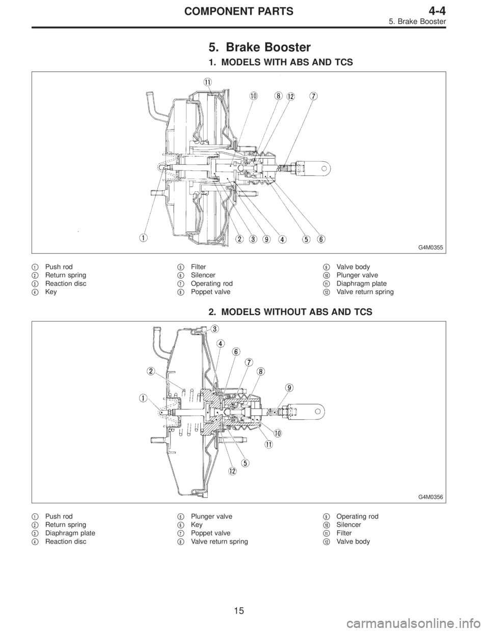
5. Brake Booster
1. MODELS WITH ABS AND TCS
G4M0355
�1Push rod
�
2Return spring
�
3Reaction disc
�
4Key�
5Filter
�
6Silencer
�
7Operating rod
�
8Poppet valve�
9Valve body
�
10Plunger valve
�
11Diaphragm plate
�
12Valve return spring
2. MODELS WITHOUT ABS AND TCS
G4M0356
�1Push rod
�
2Return spring
�
3Diaphragm plate
�
4Reaction disc�
5Plunger valve
�
6Key
�
7Poppet valve
�
8Valve return spring�
9Operating rod
�
10Silencer
�
11Filter
�
12Valve body
15
4-4COMPONENT PARTS
5. Brake Booster
 Install 1st driven gear, 1st-2nd baulk ring and gear and
hub assembly onto driven shaft.
NOTE:
Take care to install gear hub in proper direction.
2) Install 2nd driven gear bushing onto dr")
 Measure outside diameter of 1st driven gear bushing to
determine suitable 1st driven gear.
Bushing outside diameter
mm (in)1st driven gear
41.983—41.996
(1.6529—1.6534)32231AA320
41.968—41.98")
 Install ball bearing (29 x 74 x 38) on drive pinion shaft
with ST.
ST 499277100 INSTALLER
G3M0617
11) Position woodruff key in groove on the rear of drive
pinion shaft. Install 5th driven")