Page 1530 of 2890
 General precautions in handling rear gate gas stay.
CAUTION:
�Do not attempt to disassemble gas stay because its
cylinder is filled with gas.
�Before discarding gas stay, place it at a slig")
G5M0551
9) General precautions in handling rear gate gas stay.
CAUTION:
�Do not attempt to disassemble gas stay because its
cylinder is filled with gas.
�Before discarding gas stay, place it at a slight angle
with the cylinder body side facing up and drilla2to3
mm (0.08 to 0.12 in) dia. hole to completely discharge
the content. (Gas is odorless, colorless and harmless;
however, metal powder may come out of the hole.)
G5M0491
�It is good practice to place a vinyl sack over it before
drilling the hole because oil may spurt out. Be careful
to prevent vinyl cover from becoming entangled on the
drill.
�Be careful not to scratch the exposed section of
piston rod or allow oil or paint to come in contact with
it.
�Do not attempt to rotate the extended piston rod.
10) Installation is in the reverse order of removal.
CAUTION:
�Be sure to add sealer to hinge.
�When installing rear gate, be careful not to damage
coating on body and rear gate.
G5M0404
2. LATCH
1) Remove trim panel.
2) Disengage rod from holder (= key cylinder).
3) Remove bolts from auto-door lock actuator.
4) Remove bolts from latch, and detach latch.
5) Disconnect rear gate switch connector.
6) Disconnect auto-door lock actuator connector.
7) Detach latch.
8) Installation is in the reverse order of removal.
B5M0083
3. OUTER HANDLE
1) Remove trim panel.
2) Disconnect rod from outer handle.
3) Remove two nuts used to hold outer handle to the
inside of rear gate, and detach outer handle.
CAUTION:
Be careful not to damage packing when removing
outer handle.
4) Installation is in the reverse order of removal.
28
5-2SERVICE PROCEDURE
3. Rear Gate
Page 1531 of 2890
B5M0084A
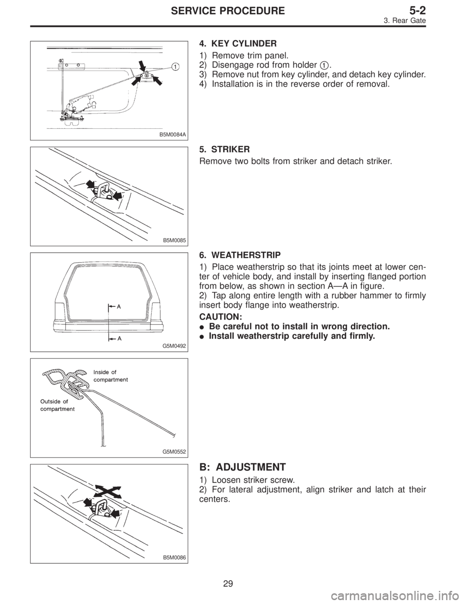
4. KEY CYLINDER
1) Remove trim panel.
2) Disengage rod from holder�
1.
3) Remove nut from key cylinder, and detach key cylinder.
4) Installation is in the reverse order of removal.
B5M0085
5. STRIKER
Remove two bolts from striker and detach striker.
G5M0492
6. WEATHERSTRIP
1) Place weatherstrip so that its joints meet at lower cen-
ter of vehicle body, and install by inserting flanged portion
from below, as shown in section A—A in figure.
2) Tap along entire length with a rubber hammer to firmly
insert body flange into weatherstrip.
CAUTION:
�Be careful not to install in wrong direction.
�Install weatherstrip carefully and firmly.
G5M0552
B5M0086
B: ADJUSTMENT
1) Loosen striker screw.
2) For lateral adjustment, align striker and latch at their
centers.
29
5-2SERVICE PROCEDURE
3. Rear Gate
Page 1657 of 2890

1. Precaution
�Before disassembling or reassembling parts, always
disconnect battery ground cable. When repairing
radio, control modules, etc. which are provided with
memory functions, record memory contents before
disconnecting battery ground cable. Otherwise, these
contents are cancelled upon disconnection.
�Reassemble parts in reverse order of disassembly
procedure unless otherwise indicated.
�Adjust parts to specifications contained in this
manual if so designated.
�Connect connectors and hoses securely during
reassembly.
�After reassembly, ensure functional parts operate
smoothly.
CAUTION:
�Airbag system wiring harness is routed near the
electrical parts and switch.
�All Airbag system wiring harness and connectors
are colored yellow. Do not use electrical test equip-
ment on these circuit.
�Be careful not to damage Airbag system wiring har-
ness when servicing the ignition key cylinder.
G6M0102
2. Battery
A: REMOVAL AND INSTALLATION
1. BATTERY
1) Disconnect the positive (+) terminal after disconnecting
the negative (�) terminal of battery.
2) Remove flange nuts from battery rods and take off bat-
tery holder.
3) Remove battery.
Tightening torque:
3.4±1.0 N⋅m (0.35±0.1 kg-m, 2.5±0.7 ft-lb)
NOTE:
�Clean battery cable terminals and apply grease to retard
the formation of corrosion.
�Connect the positive (+) terminal of battery and then the
negative (�) terminal of the battery.
4
6-2SERVICE PROCEDURE
1. Precaution - 2. Battery
Page 1658 of 2890

1. Precaution
�Before disassembling or reassembling parts, always
disconnect battery ground cable. When repairing
radio, control modules, etc. which are provided with
memory functions, record memory contents before
disconnecting battery ground cable. Otherwise, these
contents are cancelled upon disconnection.
�Reassemble parts in reverse order of disassembly
procedure unless otherwise indicated.
�Adjust parts to specifications contained in this
manual if so designated.
�Connect connectors and hoses securely during
reassembly.
�After reassembly, ensure functional parts operate
smoothly.
CAUTION:
�Airbag system wiring harness is routed near the
electrical parts and switch.
�All Airbag system wiring harness and connectors
are colored yellow. Do not use electrical test equip-
ment on these circuit.
�Be careful not to damage Airbag system wiring har-
ness when servicing the ignition key cylinder.
G6M0102
2. Battery
A: REMOVAL AND INSTALLATION
1. BATTERY
1) Disconnect the positive (+) terminal after disconnecting
the negative (�) terminal of battery.
2) Remove flange nuts from battery rods and take off bat-
tery holder.
3) Remove battery.
Tightening torque:
3.4±1.0 N⋅m (0.35±0.1 kg-m, 2.5±0.7 ft-lb)
NOTE:
�Clean battery cable terminals and apply grease to retard
the formation of corrosion.
�Connect the positive (+) terminal of battery and then the
negative (�) terminal of the battery.
4
6-2SERVICE PROCEDURE
1. Precaution - 2. Battery
Page 1663 of 2890

1) Remove instrument panel lower cover.
2) Remove lower column cover.
3) Unfasten holddown clip which secures harness, and
disconnect connector of ign")
B6M0048
B: INSPECTION
1. IGNITION SWITCH (ON-CAR)
1) Remove instrument panel lower cover.
2) Remove lower column cover.
3) Unfasten holddown clip which secures harness, and
disconnect connector of ignition switch from body harness.
4) Turn ignition key to each position and check continuity
between terminals of ignition switch connector.
Terminal
Positiona-1 a-2 a-5 a-4
LOCK
ACC��
ON���
START���
B6M0335A
4. Headlight
A: ADJUSTMENT
1. HEADLIGHT AIMING
1) Adjust the headlight aiming by turning the adjusting
screws.
CAUTION:
Before checking the headlight aiming, be sure of the
following:
�Turn off the light before adjusting headlight aiming.
If the light is necessary to check aiming, do not turn on
for more than two minutes.
�The area around the headlight has not sustained any
accident, damage or other type of deformation.
�Vehicle is parked on level ground.
�The inflation pressure of tires is correct.
�Vehicle’s gas tank is fully charged.
�Bounce the vehicle several times to normalize the
suspension.
�Make certain that someone is seated in the driver’s
seat.
NOTE:
Adjust vertical aim first, then horizontal aim.
8
6-2SERVICE PROCEDURE
3. Ignition Switch - 4. Headlight
Page 1664 of 2890

1) Remove instrument panel lower cover.
2) Remove lower column cover.
3) Unfasten holddown clip which secures harness, and
disconnect connector of ign")
B6M0048
B: INSPECTION
1. IGNITION SWITCH (ON-CAR)
1) Remove instrument panel lower cover.
2) Remove lower column cover.
3) Unfasten holddown clip which secures harness, and
disconnect connector of ignition switch from body harness.
4) Turn ignition key to each position and check continuity
between terminals of ignition switch connector.
Terminal
Positiona-1 a-2 a-5 a-4
LOCK
ACC��
ON���
START���
B6M0335A
4. Headlight
A: ADJUSTMENT
1. HEADLIGHT AIMING
1) Adjust the headlight aiming by turning the adjusting
screws.
CAUTION:
Before checking the headlight aiming, be sure of the
following:
�Turn off the light before adjusting headlight aiming.
If the light is necessary to check aiming, do not turn on
for more than two minutes.
�The area around the headlight has not sustained any
accident, damage or other type of deformation.
�Vehicle is parked on level ground.
�The inflation pressure of tires is correct.
�Vehicle’s gas tank is fully charged.
�Bounce the vehicle several times to normalize the
suspension.
�Make certain that someone is seated in the driver’s
seat.
NOTE:
Adjust vertical aim first, then horizontal aim.
8
6-2SERVICE PROCEDURE
3. Ignition Switch - 4. Headlight
Page 1667 of 2890
G6M0107
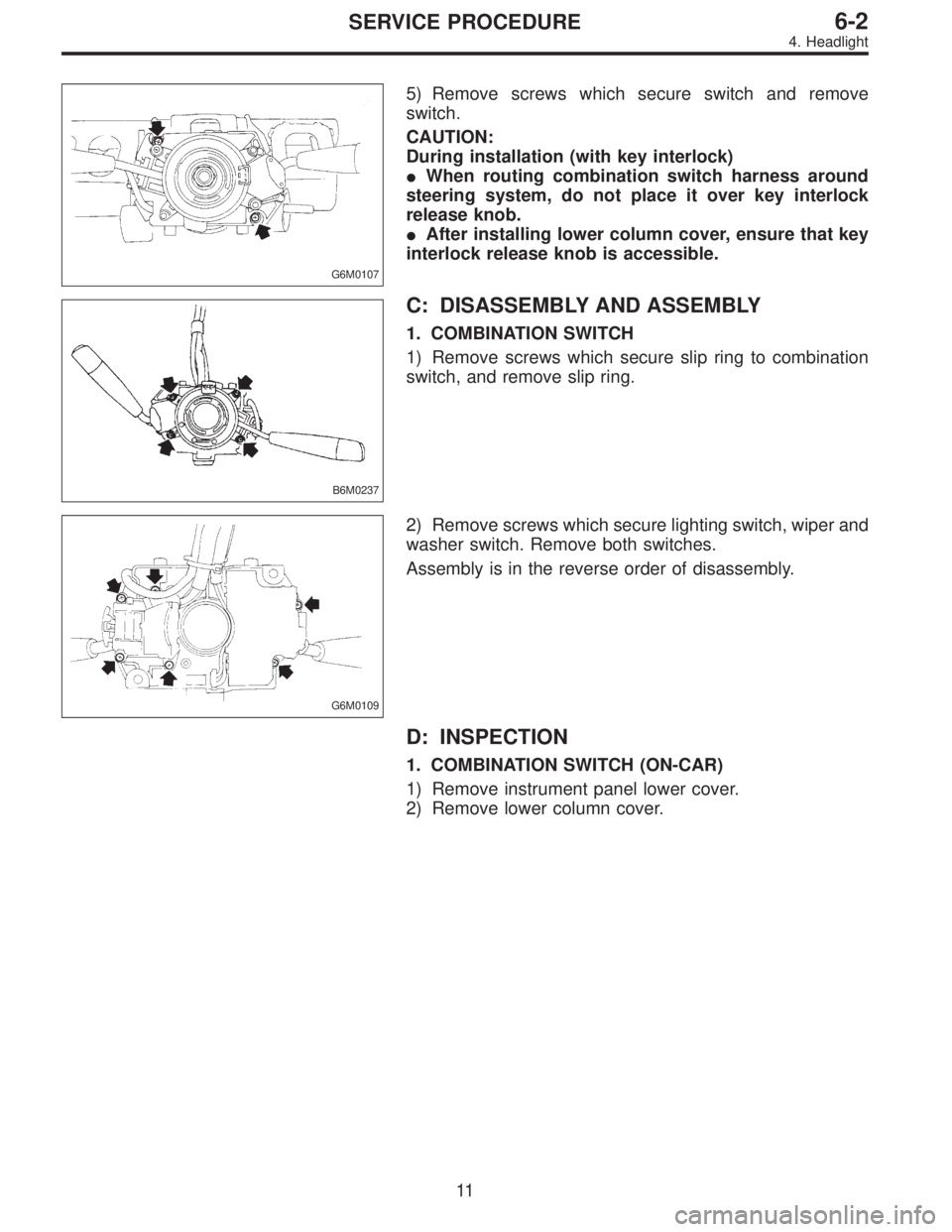
5) Remove screws which secure switch and remove
switch.
CAUTION:
During installation (with key interlock)
�When routing combination switch harness around
steering system, do not place it over key interlock
release knob.
�After installing lower column cover, ensure that key
interlock release knob is accessible.
B6M0237
C: DISASSEMBLY AND ASSEMBLY
1. COMBINATION SWITCH
1) Remove screws which secure slip ring to combination
switch, and remove slip ring.
G6M0109
2) Remove screws which secure lighting switch, wiper and
washer switch. Remove both switches.
Assembly is in the reverse order of disassembly.
D: INSPECTION
1. COMBINATION SWITCH (ON-CAR)
1) Remove instrument panel lower cover.
2) Remove lower column cover.
11
6-2SERVICE PROCEDURE
4. Headlight
Page 1696 of 2890
 Be careful not to drop or bump sensor as this may break
built-in magnet.
2) Drive key is designed to separate from vehicle speed
sensor 2. Be caref")
14. Vehicle Speed Sensor 2
A: GENERAL PRECAUTIONS
1) Be careful not to drop or bump sensor as this may break
built-in magnet.
2) Drive key is designed to separate from vehicle speed
sensor 2. Be careful not to lose it or forget to install.
3) Vehicle speed sensor 2 is installed in part (which con-
tains bearings, etc., finished to a high degree of accuracy).
Do not allow foreign matter (filings, sand, etc.) to get into
it.
4) When checking output of vehicle speed sensor 2 as a
single unit, ensure test leads are connected to their correct
terminals. Failure to do this may damage internal IC.
5) Discard vehicle speed sensor 2 after removal; replace
with new one.
B: REMOVAL
CAUTION:
�Be careful when removing vehicle speed sensor 2
immediately after driving vehicle for a while, as tem-
perature around it is high.
�Before removing vehicle speed sensor 2, clean dirt,
etc. from surrounding areas. Take care not to allow
foreign matter to get into mounting hole.
B2M0211
1) Remove collector cover.
2) Disconnect vehicle speed sensor 2 connector.
3) Turn and remove vehicle speed sensor 2.
4) Remove key and packing.
35
6-2SERVICE PROCEDURE
14. Vehicle Speed Sensor 2