Page 1763 of 2890
B6M0446A
Trunk lid (SEDAN)
Connector & terminal / Specified voltage:
(B93) No. 15—Body/1V,max.
(UNLOCK position)
/ 10 V, or more (other than
UNLOCK position)
B6M0409A
3) Measure voltage between security control module con-
nector and body while removing/installing key cylinder
switch from/to door outer handle.
Connector & terminal / Specified voltage:
(B93) No. 3—Body / 10 V, or more
(Switch is installed.)
/ 1 V, max.
(Switch is removed.)
NOTE:
For SEDAN vehicles, remove key cylinder switch from
trunk lid key cylinder to perform the above inspection.
2. CHECK KEY CYLINDER SWITCH.
Refer to 6-2 [W22B4] for inspection of key cylinder lock/
unlock switch and tamper switch.
99
6-2DIAGNOSTICS
6. Security System
Page 1764 of 2890

L: DIAGNOSTICS PROCEDURE FOR
STARTER INTERRUPT SIGNAL
1. Check starter interrupt output signal for security
control module.
Not OK
�OK
5. Check starter interrupt relay.
OK Not OK
Repair or replace
wiring harness of
starter motor circuit.
Replace starter
interrupt relay.
2. Check power supply for starter interrupt relay.
OK
�Not OK
Repair or replace wiring harness between starter
interrupt relay and battery.
3. Check continuity of starter interrupt relay.
OK
�Not OK
Replace starter interrupt relay.
4. Check harness connector between starter
interrupt relay and security control module.
OK
�Not OK
Repair or replace wiring harness between starter
interrupt relay and security control module.
Replace security control module.
B6M0445A
1. CHECK STARTER INTERRUPT OUTPUT SIGNAL
FOR SECURITY CONTROL MODULE.
1) Remove security control module without disconnecting
connector.
2) Measure voltage between security control module con-
nector and body.
Connector & terminal / Specified voltage:
(B93) No. 5—Body / 10 V, or more
3) Set security system in armed state.
4) Open the door without ignition key to operate the secu-
rity system (alarm state).
5) Measure voltage between security control module and
body during alarm state.
Connector & terminal / Specified voltage:
(B93) No. 5—Body/1V,max.
��
�
�
�
�
100
6-2DIAGNOSTICS
6. Security System
Page 1766 of 2890

M: DIAGNOSTICS PROCEDURE FOR HORN
ALARM SIGNAL
1. Check horn alarm output signal for security
control module.
Not OK
�OK
5. Check horn relay.
OK Not OK
Repair or replace
wiring harness of horn
circuit.
Replace horn relay.
2. Check power supply for horn relay.
OK
�Not OK
Repair or replace wiring harness between horn
relay and battery.
3. Check continuity of horn relay.
OK
�Not OK
Replace horn relay.
4. Check harness connector between horn relay
and security control module.
OK
�Not OK
Repair or replace wiring harness between horn
relay and security control module.
Replace security control module.
B6M0461A
1. CHECK HORN ALARM OUTPUT SIGNAL FOR
SECURITY CONTROL MODULE.
1) Remove security control module without disconnecting
connector.
2) Measure voltage between security control module con-
nector and body.
Connector & terminal / Specified voltage:
(B93) No. 13—Body / 10 V, or more
3) Set security system in armed state.
4) Open the door without ignition key to operate the secu-
rity system (alarm state).
5) Measure voltage between security control module and
body during alarm state.
Connector & terminal / Specified voltage:
(B93) No. 13—Body / repeats 1 V, max. (0.2 sec.)
and 10 V, or more (0.6 sec.)
intervals
��
�
�
�
�
102
6-2DIAGNOSTICS
6. Security System
Page 1768 of 2890

N: DIAGNOSTICS PROCEDURE FOR
HEADLIGHT ALARM SIGNAL
1. Check headlight alarm output signal for security
control module.
Not OK
�OK
5. Check headlight alarm relay.
OK Not OK
Repair or replace
wiring harness of
headlight circuit.
Replace headlight
alarm relay.
2. Check power supply for headlight alarm relay.
OK
�Not OK
Repair or replace wiring harness between
headlight alarm relay and battery.
3. Check continuity of headlight alarm relay.
OK
�Not OK
Replace headlight alarm relay.
4. Check harness connector between headlight
alarm relay and security control module.
OK
�Not OK
Repair or replace wiring harness between
headlight alarm relay and security control
module.
Replace security control module.
B6M0457A
1. CHECK HEADLIGHT ALARM OUTPUT SIGNAL
FOR SECURITY CONTROL MODULE.
1) Remove security control module without disconnecting
connector.
2) Measure voltage between security control module con-
nector and body.
Connector & terminal / Specified voltage:
(B93) No. 12—Body / 10 V, or more
3) Set security system in armed state.
4) Open the door without ignition key to operate the secu-
rity system (alarm state).
5) Measure voltage between security control module and
body during alarm state.
Connector & terminal / Specified voltage:
(B93) No. 12—Body / repeats 1 V, max. (0.2 sec.)
and 10 V, or more (0.6 sec.)
intervals
��
�
�
�
�
104
6-2DIAGNOSTICS
6. Security System
Page 1801 of 2890
OBD0060
5) Turn ignition switch to ON (engine OFF) and Subaru
select monitor switch to ON.
6) Using Subaru select monitor, call up diagnostic trouble
code(s) and various data, then record them.
H2M1149
2. READ DIAGNOSTIC TROUBLE CODE (DTC)
SHOWN ON DISPLAY. (MODE FB1)
1) Select engine mode using function key.
Press the function key [0].
G3M0152
2) Designate mode using function key.
Press [F] [B] [1] [ENT] in that order.
OBD0062
3) Ensure diagnostic trouble code(s) is shown.
(1) When there is only one diagnostic trouble code.
OBD0063
(2) When there are multiple diagnostic trouble codes.
NOTE:
For details concerning diagnostic trouble codes, refer to
the DIAGNOSTIC TROUBLE CODE (DTC) LIST, 2-7
[T10A0].
33
2-7ON-BOARD DIAGNOSTICS II SYSTEM
3. Diagnosis System
Page 1802 of 2890
H2M1149
3. READ CURRENT DATA SHOWN ON DISPLAY FOR
ENGINE. (FUNCTION MODE)
1) Select engine mode using function key.
Press the function key [0].
G3M0152
2) Designate mode using function key.
Refer to“6. READ DATA FUNCTION KEY LIST FOR
ENGINE”2-7 [T3C6].
(Example: Press [F] [0] [1] [ENT] in that order.)
3) Ensure data of input or output signal is shown.
H2M1149
4. READ FREEZE FRAME DATA SHOWN ON
DISPLAY. (MODE FB2)
1) Select engine mode using function key.
Press the function key [0].
G3M0152
2) Designate mode using function key.
Press [F] [B] [2] [ENT] in that order.
B2M0474
3) Ensure freeze frame data(s) is (are) shown.
(1) When no trouble is detected, or after memory is
cleared.
34
2-7ON-BOARD DIAGNOSTICS II SYSTEM
3. Diagnosis System
Page 1803 of 2890
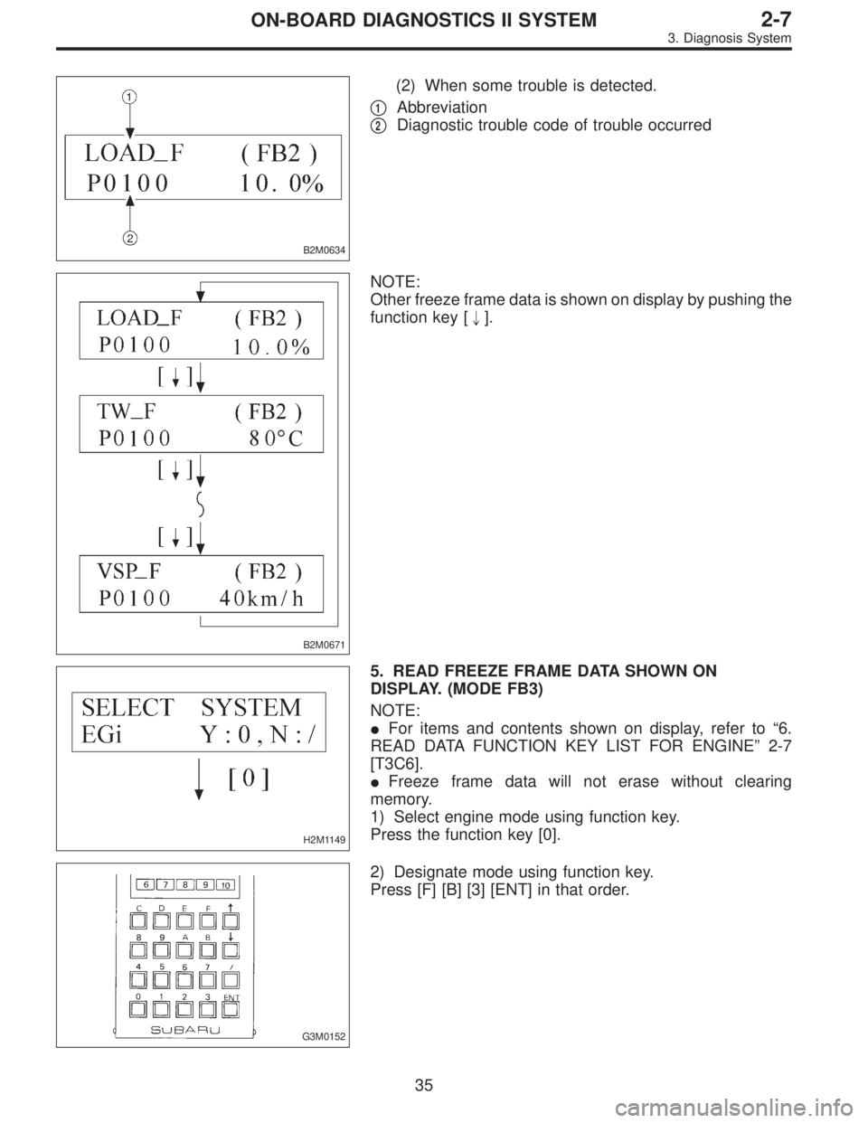
B2M0634
(2) When some trouble is detected.
�
1Abbreviation
�
2Diagnostic trouble code of trouble occurred
B2M0671
NOTE:
Other freeze frame data is shown on display by pushing the
function key ["].
H2M1149
5. READ FREEZE FRAME DATA SHOWN ON
DISPLAY. (MODE FB3)
NOTE:
�For items and contents shown on display, refer to“6.
READ DATA FUNCTION KEY LIST FOR ENGINE”2-7
[T3C6].
�Freeze frame data will not erase without clearing
memory.
1) Select engine mode using function key.
Press the function key [0].
G3M0152
2) Designate mode using function key.
Press [F] [B] [3] [ENT] in that order.
35
2-7ON-BOARD DIAGNOSTICS II SYSTEM
3. Diagnosis System
Page 1805 of 2890

6. READ DATA FUNCTION KEY LIST FOR ENGINE
Function mode Contents Abbreviation Unit of measure
F00 ROM ID number YEAR—
F01 Battery voltage VB V
F02 Vehicle speed signal VSP km/h, MPH
F03 Engine speed signal EREV rpm
F04 Engine coolant temperature signal TW°C,°F
F05 Ignition signal ADVS deg
F06 Mass air flow signal QA g/s, V
F07 Throttle position signal THV %, V
F08 Injector pulse width TIM mS
F09 Idle air control signal ISC %
F10 Load data LOAD %
F11 Front oxygen sensor output signal O2 V
F12 Front oxygen sensor maximum and minimum output signal O2max - min V, V
F13 Rear oxygen sensor output signal RO2 V
F14 Rear oxygen sensor maximum and minimum output signal RO2max - min V, V
F17 Short term fuel trim ALPHA %
F19 Knock sensor signal KNOCK deg
F20 Atmospheric absolute pressure signal BARO. P kPa, mmHg
F21 Intake manifold absolute pressure signal MANI. P kPa, mmHg
F29 A/F correction (short term trim) by rear oxygen sensor PHOS %
F30 Long term fuel trim KBLRC %
F31 Long term whole fuel trim K0 %
F32 Front oxygen sensor heater current FO2H A
F33 Rear oxygen sensor heater current RO2H A
F35 Purge control solenoid valve duty ratio CPCD %
F36Maximum value of cylinder #1 misfire times during 100 rota-
tionsMF1 %
F37Maximum value of cylinder #2 misfire times during 100 rota-
tionsMF2 %
F38Maximum value of cylinder #3 misfire times during 100 rota-
tionsMF3 %
F39Maximum value of cylinder #4 misfire times during 100 rota-
tionsMF4 %
F42Maximum and minimum EGR system pressure value (AT
vehicles only)EGRmax - min kPa
F43 Fuel tank pressure signal TNKP kPa, mmHg
F44 Fuel temperature signal TNKT°C,°F
F45 Fuel level signal FLEVEL V
FA 0 O N)OFF signal——
FA 1 O N)OFF signal——
FA 2 O N)OFF signal——
FA 3 O N)OFF signal——
FA 4 O N)OFF signal——
FA 5 O N)OFF signal——
FB0 Diagnostic trouble code (DTC) INSPECT—
FB1 Diagnostic trouble code (DTC) OBD—
37
2-7ON-BOARD DIAGNOSTICS II SYSTEM
3. Diagnosis System

Connector & terminal / Specified voltage:
(B93) No. 15—Body/1V,max.
(UNLOCK position)
/ 10 V, or more (other than
UNLOCK position)
B6M0409A
3) Measure voltage between secu")
 Turn ignition switch to ON (engine OFF) and Subaru
select monitor switch to ON.
6) Using Subaru select monitor, call up diagnostic trouble
code(s) and various data, then record them.
H2M114")
![SUBARU LEGACY 1996 Service Repair Manual H2M1149
3. READ CURRENT DATA SHOWN ON DISPLAY FOR
ENGINE. (FUNCTION MODE)
1) Select engine mode using function key.
Press the function key [0].
G3M0152
2) Designate mode using function key.
Refer to�](/manual-img/17/57433/w960_57433-1801.png "SUBARU LEGACY 1996 Service Repair Manual H2M1149
3. READ CURRENT DATA SHOWN ON DISPLAY FOR
ENGINE. (FUNCTION MODE)
1) Select engine mode using function key.
Press the function key [0].
G3M0152
2) Designate mode using function key.
Refer to�")