Page 1692 of 2890
G6M0112
2. DEFOGGER RELAY
Check continuity between terminals as indicated in table
below, when connecting the battery to terminal No. 1 and
No. 3.
When current flows.Between terminals
No. 2 and No. 4Continuity exists.
When current does not flow.Between terminals
No. 2 and No. 4Continuity does not
exist.
Between terminals
No. 1 and No. 3Continuity exists.
G6M0135
3. HEAT WIRES
1) Start the engine so that battery is being charged.
2) Turn defogger switch to ON.
3) Check each heat wire at its center position for discon-
tinuity by setting direct current voltmeter.
Normal indication is about 6 volts.
G6M0136
NOTE:
When measuring voltage, wind a piece of tin foil around the
tip of the tester probe and press the foil against the wire
with your finger.
32
6-2SERVICE PROCEDURE
12. Rear Window Defogger
Page 1693 of 2890
 When tester indicates 12 volts when its probe reaches
point“A”, a broken circuit occurs between point“A”and the
negative terminal. Slowly move tester probe toward the
negative termi")
G6M0137
4) When tester indicates 12 volts when its probe reaches
point“A”, a broken circuit occurs between point“A”and the
negative terminal. Slowly move tester probe toward the
negative terminal while contacting it on heat wire to locate
point where tester indication changes abruptly (0 volts).
This is the point where a broken circuit occurs.
When tester indicates 0 volts when its probe reaches point
“A”, a broken circuit occurs between point“A”and the posi-
tive terminal. Locate a point where tester indication
changes abruptly (12 volts) while slowly moving tester
probe toward the positive terminal.
G6M0138
C: REPAIR
1) Clean broken wire and its surrounding area.
2) Cut off slit on (used) thin film by 0.5 mm (0.020 in) width
and 10 mm (0.39 in) length.
3) Place the slit on glass along the broken wire, and
deposit conductive silver composition (DUPONT No. 4817)
on the broken portion.
4) Dry out the deposited portion.
5) Inspect the repaired wire for continuity.
B6M0120
13. Combination Meter
A: REMOVAL AND INSTALLATION
1. COMBINATION METER
1) Move steering wheel fully down.
2) Remove screws which secure meter visor.
3) Remove visor from instrument panel.
4) Disconnect connectors from meter visor.
B6M0121
5) Remove screws which secure combination meter, and
pull combination meter out.
6) Disconnect connectors from back of combination meter.
CAUTION:
When installing combination meter, be sure to connect
connectors to backside of combination meter.
33
6-2SERVICE PROCEDURE
12. Rear Window Defogger - 13. Combination Meter
Page 1694 of 2890
 When tester indicates 12 volts when its probe reaches
point“A”, a broken circuit occurs between point“A”and the
negative terminal. Slowly move tester probe toward the
negative termi")
G6M0137
4) When tester indicates 12 volts when its probe reaches
point“A”, a broken circuit occurs between point“A”and the
negative terminal. Slowly move tester probe toward the
negative terminal while contacting it on heat wire to locate
point where tester indication changes abruptly (0 volts).
This is the point where a broken circuit occurs.
When tester indicates 0 volts when its probe reaches point
“A”, a broken circuit occurs between point“A”and the posi-
tive terminal. Locate a point where tester indication
changes abruptly (12 volts) while slowly moving tester
probe toward the positive terminal.
G6M0138
C: REPAIR
1) Clean broken wire and its surrounding area.
2) Cut off slit on (used) thin film by 0.5 mm (0.020 in) width
and 10 mm (0.39 in) length.
3) Place the slit on glass along the broken wire, and
deposit conductive silver composition (DUPONT No. 4817)
on the broken portion.
4) Dry out the deposited portion.
5) Inspect the repaired wire for continuity.
B6M0120
13. Combination Meter
A: REMOVAL AND INSTALLATION
1. COMBINATION METER
1) Move steering wheel fully down.
2) Remove screws which secure meter visor.
3) Remove visor from instrument panel.
4) Disconnect connectors from meter visor.
B6M0121
5) Remove screws which secure combination meter, and
pull combination meter out.
6) Disconnect connectors from back of combination meter.
CAUTION:
When installing combination meter, be sure to connect
connectors to backside of combination meter.
33
6-2SERVICE PROCEDURE
12. Rear Window Defogger - 13. Combination Meter
Page 1699 of 2890
 Burned or shorted contacts
2) Broken or weak spring
3) Damaged harness
4) Worn or corroded mating surface of")
B: INSPECTION
1. HORN SWITCH
Ensure that horn switch is free from the following defects:
1) Burned or shorted contacts
2) Broken or weak spring
3) Damaged harness
4) Worn or corroded mating surface of horn plate
B6M0126A
2. HORN RELAY
Check continuity between terminals as indicated in table
below, when connecting the battery to terminals No. 1 and
No. 2.
When current flows. Between terminals
No. 2 and No. 3Continuity exists.
When current does not flow. Between terminals
No. 2 and No. 3Continuity does not
exist.
Between terminals
No. 1 and No. 2Continuity exists.
B6M0127
3. HORN
Make sure that horn sounds when battery voltage is
applied between connector terminal and horn body.
4. CIGARETTE LIGHTER
1) Remove plug. Then, check element’s contact for wear,
and element for accumulation of ashes, foreign particles,
etc.
2) Check element for discontinuity.
3) Remove socket and clean element. Then, check for
wear or foreign particles on element’s contact and mating
surface.
4) Ensure that cigarette lighter returns within 20 seconds
after it is turned to ON.
16. Power Window
A: REMOVAL AND INSTALLATION
1. MAIN SWITCH, SUB SWITCH AND POWER
WINDOW MOTOR
Refer to 5-2 [W2A2] as for removal and installation of
power window main switch, sub switch and motor.
NOTE:
To remove the power window motor, it is necessary to dis-
assemble the door component parts.
38
6-2SERVICE PROCEDURE
15. Horn and Cigarette Lighter - 16. Power Window
Page 1700 of 2890
 Burned or shorted contacts
2) Broken or weak spring
3) Damaged harness
4) Worn or corroded mating surface of")
B: INSPECTION
1. HORN SWITCH
Ensure that horn switch is free from the following defects:
1) Burned or shorted contacts
2) Broken or weak spring
3) Damaged harness
4) Worn or corroded mating surface of horn plate
B6M0126A
2. HORN RELAY
Check continuity between terminals as indicated in table
below, when connecting the battery to terminals No. 1 and
No. 2.
When current flows. Between terminals
No. 2 and No. 3Continuity exists.
When current does not flow. Between terminals
No. 2 and No. 3Continuity does not
exist.
Between terminals
No. 1 and No. 2Continuity exists.
B6M0127
3. HORN
Make sure that horn sounds when battery voltage is
applied between connector terminal and horn body.
4. CIGARETTE LIGHTER
1) Remove plug. Then, check element’s contact for wear,
and element for accumulation of ashes, foreign particles,
etc.
2) Check element for discontinuity.
3) Remove socket and clean element. Then, check for
wear or foreign particles on element’s contact and mating
surface.
4) Ensure that cigarette lighter returns within 20 seconds
after it is turned to ON.
16. Power Window
A: REMOVAL AND INSTALLATION
1. MAIN SWITCH, SUB SWITCH AND POWER
WINDOW MOTOR
Refer to 5-2 [W2A2] as for removal and installation of
power window main switch, sub switch and motor.
NOTE:
To remove the power window motor, it is necessary to dis-
assemble the door component parts.
38
6-2SERVICE PROCEDURE
15. Horn and Cigarette Lighter - 16. Power Window
Page 1701 of 2890
B6M0128A
B: INSPECTION
1. MAIN SWITCH
Set power window main switch to each position and check
continuity between terminals as indicated in table below:
LHD model
Window lock switchSwitch
PositionFront RH Front LH Rear RH Rear LH
7 14 9 12 7 13 8 12 7 6 11 12 7 10 5 12
NORMALUP��
��������������
OFF������������
DOWN��������
��������
LOCKUP��
��������
OFF���������
DOWN����������
RHD model
Window lock switchSwitch
PositionFront RH Front LH Rear RH Rear LH
7 11 6 12 7 10 5 12 7 9 14 12 7 13 8 12
AUTO UP��
��
UP����������������
OFF������������
DOWN��������
��������
AUTO DOWN����
39
6-2SERVICE PROCEDURE
16. Power Window
Page 1702 of 2890
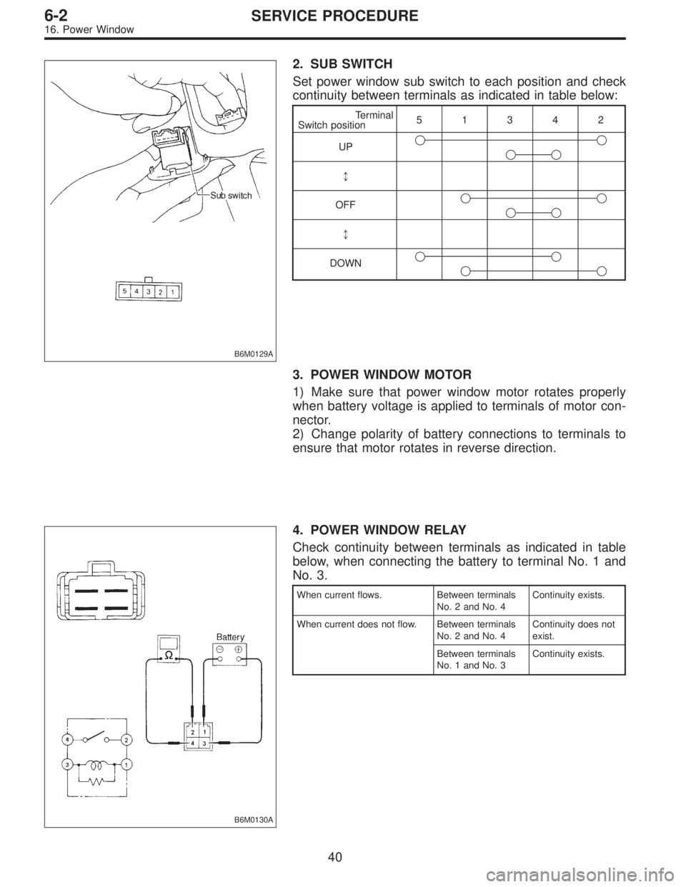
B6M0129A
2. SUB SWITCH
Set power window sub switch to each position and check
continuity between terminals as indicated in table below:
Terminal
Switch position51342
UP��
��
*
OFF��
��
*
DOWN��
��
3. POWER WINDOW MOTOR
1) Make sure that power window motor rotates properly
when battery voltage is applied to terminals of motor con-
nector.
2) Change polarity of battery connections to terminals to
ensure that motor rotates in reverse direction.
B6M0130A
4. POWER WINDOW RELAY
Check continuity between terminals as indicated in table
below, when connecting the battery to terminal No. 1 and
No. 3.
When current flows. Between terminals
No. 2 and No. 4Continuity exists.
When current does not flow. Between terminals
No. 2 and No. 4Continuity does not
exist.
Between terminals
No. 1 and No. 3Continuity exists.
40
6-2SERVICE PROCEDURE
16. Power Window
Page 1724 of 2890
 Fully open all the door windows.
2) Turn the ignition switch to OFF and remove ignition key
from ignition switch.
3) Get out of the vehicle and lock th")
C: FUNCTION TEST
1. SECURITY SYSTEM OPERATION
1) Fully open all the door windows.
2) Turn the ignition switch to OFF and remove ignition key
from ignition switch.
3) Get out of the vehicle and lock the driver’s door using a
ignition key.
4) Check that the security indicator light illuminates.
5) When the security indicator light illuminates, wait for 30
seconds.
After 30 seconds, check that the light starts repeating 0.2
sec. ON and 2.4 sec. OFF sequence.
6) Unlock the driver’s door using the inside lock knob and
open the door.
Ensure that:
(1) the horn sounds and headlights flash intermittently
at 0.2 sec. ON and 0.6 sec. OFF. intervals, and
(2) the engine will not start even if the ignition switch
is turned to START.
7) Unlock the driver’s door one time using the ignition key.
Ensure the horn and headlights turn off.
8) Close and lock the driver’s door without using a ignition
key. (Set the inside lock knob to LOCK and then close the
door while lifting the outer handle).
Check that the security indicator light illuminates continu-
ously.
9) Within 30 seconds after the above step 8), unlock the
rear LH door using the inside lock knob and open the door.
Check that the security indicator light flashes at 0.5 sec.
intervals.
10) Close the rear LH door and lock the door using the
inside lock knob.
Check that the security indicator light illuminates continu-
ously.
11) Perform the above steps 9) and 10) on the rear RH
door and front RH door.
12) Within 30 seconds after above step 11) has been
finished, pull the engine hood opener lever and open the
engine hood.
Check that the security indicator light flashes at 0.5 sec.
intervals.
13) Close the engine hood completely.
Check that the security indicator light illuminates continu-
ously.
60
6-2SERVICE PROCEDURE
22. Security System