1996 SUBARU LEGACY window
[x] Cancel search: windowPage 2 of 2890
SPECIFICATIONS
[s21o1
1-1
2
.
Station
Wagon
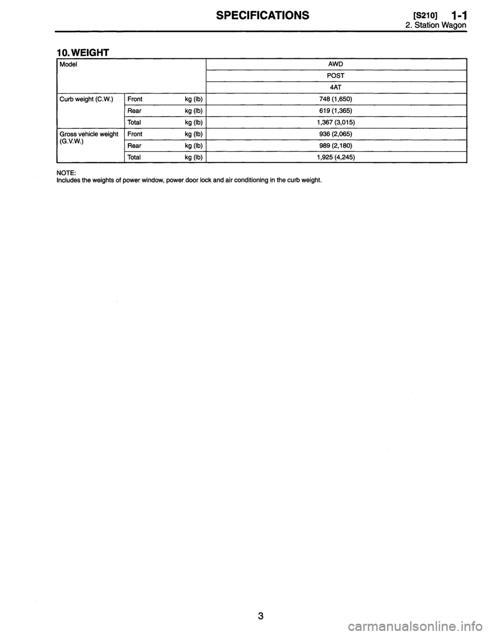
10
.
WEIGHT
Model
AWD
POST
4AT
Curb
weight
(C
.W
.)
Front
kg
(1b)
748
(1,650)
Rear
kg
(1b)
619
(1,365)
Total
kg
(1b)
1,367
(3,015)
Gross
vehicle
weight
Front
kg
(1b)
936
(2,065)
(G
.V
.W
.)
Rear
kg
(1b)
9S9
(2,180)
Total
kg
(1b)
1,925
(4,245)
NOTE
:
Includes
the
weights
of
power
window,
power
door
lock
and
air
conditioning
in
the
curb
weight
.
Page 175 of 2890
![SUBARU LEGACY 1996 Service Repair Manual
s-$
[D601]
WIRING
DIAGRAM
6
.
Wiring
Diagram
No
.
Load
MB-2
Powerwindow
circuit
breaker
Engine
control
module
Fuel
pump
relay
MB-3
Main
relay
OBD-II
service
connector
MB-4A/C
relay
holder
MB- SUBARU LEGACY 1996 Service Repair Manual
s-$
[D601]
WIRING
DIAGRAM
6
.
Wiring
Diagram
No
.
Load
MB-2
Powerwindow
circuit
breaker
Engine
control
module
Fuel
pump
relay
MB-3
Main
relay
OBD-II
service
connector
MB-4A/C
relay
holder
MB-](/manual-img/17/57433/w960_57433-174.png)
s-$
[D601]
WIRING
DIAGRAM
6
.
Wiring
Diagram
No
.
Load
MB-2
Powerwindow
circuit
breaker
Engine
control
module
Fuel
pump
relay
MB-3
Main
relay
OBD-II
service
connector
MB-4A/C
relay
holder
MB-6
Headlight
LH
Diode
(Lighting)
Lighting
switch
Combination
meter
M
B_$
Headlight
RH
Combination
meter
Door
lock
timer
MB-9
Luggage
room
light
Radio
Room
light
MB-10
A/C
relay
holder
ALT-1
Combination
meter
IG
A/C
relay
holder
Cruise
control
module
ST
Engine
control
module
Inhibitor
switch
FB-2
Diode
(A/C)
Sub
fan
motor
FB-3
Sub
fan
relay-2
Engine
control
module
Fuel
pump
relay
FB-4
Ignition
coil
Transmission
control
module
Side
marker
light
LH
FB-6
Side
marker
light
RH
FB-7Door
lock
timer
FB-9Hazard
switch
AT
shift
lock
control
module
FB-10
Key
warning
switch
Power
antenna
FB-11
Radio
FB-12
Cigarette
lighter
FB-13
Remote
control
rearview
mirrorswitch
AT
shift
lock
control
module
Combination
switch
Front
washer
motor
FB-14
Front
wipermotor
Rear
washer
motor
Rear
wipermotor
Rear
wiper
relay
FB-15Transmission
control
module
Na
Load
Rear
defogger
FB-16
Rear
defogger
condenser
Reardefogger
switch
FB-17
Rear
defogger
switch
FB-18
AT
shift
lock
control
module
Inhibitor
switch
FB-19
Hazard
switch
Combination
meter
FB-20
Mode
control
panel
FB-21
Combination
meter
(Airbag)
Blower
motor
relay
Check
connector
FB-22
FRESH/RECIRC
actuator
Mode
actuator
Powerwindow
relay
Seat
belt
timer
FB-23
Airbag
.
control
module
FB-24
Airbag
control
module
FB-25
Lighting
switch
FB-26
Parking
switch
FB-27
Parking
switch
FB-28
Illumination
light
FB-29
Illumination
light
FB-30
Stop
light
switch
Stop
&
brake
switch
FB-31
Horn
relay
FB-32
Blower
motor
relay
FB-33
Parking
switch
License
plate
light
LH
License
plate
light
RH
FB-34
Rear
combination
light
LH
Rear
combination
light
RH
Rear
finisher
light
LH
Rear
finisher
light
RH
FB-35
Cruise
control
main
switch
Cruise
control
module
Page 190 of 2890
r
Connecting
to
)r
Area
No
.
Name
C-4
D1
Front
doorcord
RH
ow
C-4
ABi
SRS
(Airbag)
harness
;k
C-4
Turn
&
hazard
module
.k
C-3
i1
C-3
i2
instrument
panel
wiring
un
C-3
i3
harness
e
C-3
i4
y
C-3
OBD-IIservice
connector
C-3
Power
window
circuit
breaker
C-3
Power
window
relay
;k
C-3
Illuminationcontrol
module
C-3
Seat
belt
timer
;n
B-4
Fuel
pump
relay
vn
B-4
Main
relay
;k
B-4
Horn
relay
B-4
Blower
relay
y
C-4
FIB
y
C-4
B-3
Shield
joint
connector
(AT)
.k
B-3
:k
B-3
Transmission
control
module
.k
B-3
:k
B-3
Shift-lock
control
module
B-4F44
i
h
B-4F45
Front
w
ring
arness
.k
B-3
Stop
light
switch
,k
B-3
Stop
8
brake
switch
(Withcruise
control)
:k
8-3
Cruise
control
sub
switch
Connector
Connecting
to
No
.
Pole
Color
Area
No
.
Name
869
11
Black
C-3
B70
9
C-3
Combination
switch
B71
8
8-3
B72
6
Black
C-3
Ignition
switch
B73
2
Black
B-3
Key
lock
solenoid
B74
2
Black
B-3
Key
warning
switch
B75
2
Green
B-2
876
T
d
B76
2
Green
8-2
875
e
connector
est
mo
877
7
B-2
Mode
actuator
B78
9
Yellow
B-2
Data
link
connector
B79
14
Gray
C-2
Check
connector
BBO
4
Blue
B-2
i20
Instrument
panel
wiring
harness
B81
1
x
2
B-2
Diagnosis
terminal
(Ground)
B82
6
Black
B-2
Diagnosisconnector
BB3
4
C-1
Shield
joint
connector
(EIG)
BBQ
96Lightblue
C-2
Engine
control
module
B85
4
Brown
B-3
Diode
(Lighting)
B86
4
Black
B-1
Blower
motor
resistor
887
2
Black
B-1
Blower
motor
888
3
Black
B-1
Evaporatorthermoswitch
B90
2
Green
B-4
R50
Room
light
cord
B91
5
B-1
FRESHIRECIRC
actuator
B92
8
B-1
Door
lock
timer
894
20
Black
B-1
Cruise
control
module
B97
56
B-4
R1
Rear
wiring
harness
(S.M
.J
.)
B101
24
B-1
D11
Front
door
cord
LH
8111
3
Gray
C-4FIB
`
:
Non-colored
4
.
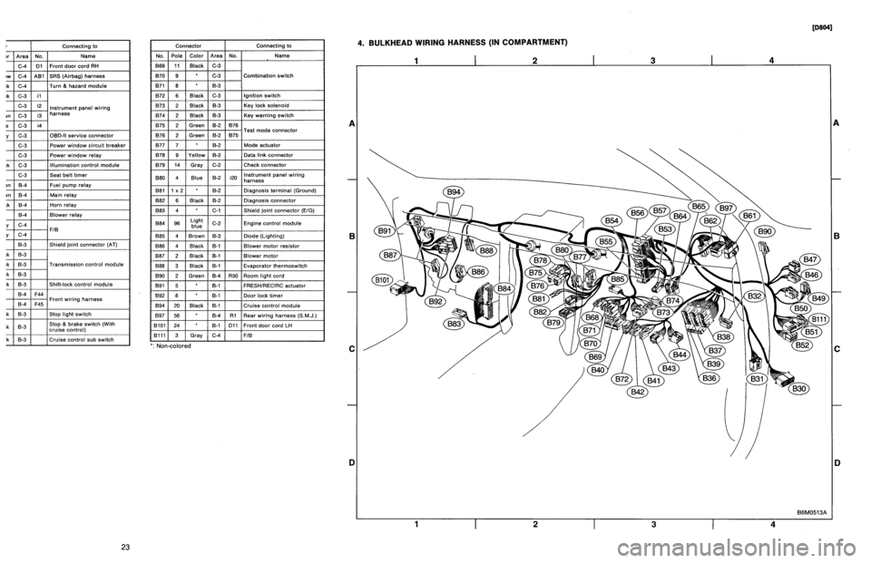
BULKHEAD
WIRING
HARNESS
(IN
COMPARTMENT)
1
I
2
I
3
I
4
A
B
C
D
1
I
2
I
3
I
4
[oeo41
B6M0513A
A
B
C
iJ
23
Page 191 of 2890
Connector
Connecting
to
No
.
Pole
Color
Area
No
.
Name
830
24
C-4
D1
Front
door
cord
RH
831
7
Yellow
C-4
A81
SRS
(Airbag)
harness
B32
3
Black
C-4
Turn
&
hazard
module
B36
22
Black
C-3
i1
B37
22
C-3
i2
Instrument
panel
wiring
B38
22
Brown
C-3
i3
harness
B39
20Blue
C-3
i4
B40
16
Gray
C-3
OBD-II
service
connector
B41
2
C-3
Power
window
circuit
breaker
842
4
C-3
Power
window
relay
B43
6
Black
C-3
Illumination
control
module
B44
8
C-3
Seat
belt
timer
B46
4
Green
B-4
Fuel
pump
relay
B47
6
Brown
B-4
Main
relay
B49
3
Black
B-4
Horn
relay
850
4
B-4
Blower
relay
851
11
Gray
C-4
FIB
B52
12
Gray
C-4
853
4
B-3
Shield
joint
connector
(AT)
B54
12
Black
B-3
B55
16
Black
B-3
Transmission
control
module
B56
20
Black
B-3
B57
12
Black
B-3
Shift-lock
control
module
861
B
B-4
F44
B62
20
B-4
F45
Front
wiring
harness
B64
2
Black
B-3
Stop
light
switch
B65
4
Black
B-3
Stop
&
brake
switch(Withcruise
control)
B68
5
i
Black
i
B-3
Cruise
control
sub
switch
Connector
Connecting
to
No
.
Pole
Color
Area
No
.
Name
B69
11
Black
C-3
B70
9
C-3
Combination
switch
B71
8
8-3
B72
6
Black
C-3
Ignition
switch
B73
2
Black
B-3
Key
lock
solenoid
B74
2
Black
B-3
Key
warning
switch
B75
2
Green
B-2
B76
B76
2
Green
&2
B75
Test
mode
connector
B77
7
B-2
Made
actuator
B78
9
Yellow
B-2
Data
link
connector
B79
14
Gray
C-2
Check
connector
B80
4
Blue
B-2
i20
Instrumentpanel
wiring
harness
B81
1
x
2
B-2
Diagnosis
terminal
(Ground)
B82
6
Black
B-2
Diagnosis
connector
B83
4
C-1
Shield
joint
connector
(E!G)
884
96
Light
blue
C-2
Engine
control
module
885
4
Brown
B-3
Diode
(Lighting)
B86
4
Black
B-1
Blower
motor
resistor
887
2
Black
B-1
Blower
motor
B88
3
Black
8-t
Evaporator
thermoswitch
890
2
Green
B-4
R50
Room
light
cord
B91
5B-1
FRESHIRECIRC
actuator
892
8
B-1
Door
lock
timer
B94
20
Black
B-1
Cruise
control
module
B97
56
B-4
R1Rear
wiring
harness
(S
.M
.J
.)
B101
24
B-1
D11
Front
doorcord
LH
13111
3
Gray
C-4
FIB
`
:
Non-colored
4
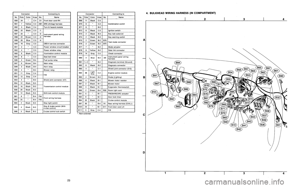
.
BULKHEAD
WIRING
HARNESS
(IN
COMPARTMENT)
A
B
C
1]
4
23
Page 720 of 2890
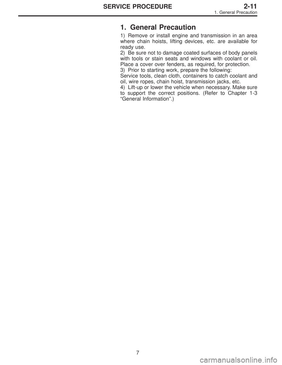
1. General Precaution
1) Remove or install engine and transmission in an area
where chain hoists, lifting devices, etc. are available for
ready use.
2) Be sure not to damage coated surfaces of body panels
with tools or stain seats and windows with coolant or oil.
Place a cover over fenders, as required, for protection.
3) Prior to starting work, prepare the following:
Service tools, clean cloth, containers to catch coolant and
oil, wire ropes, chain hoist, transmission jacks, etc.
4) Lift-up or lower the vehicle when necessary. Make sure
to support the correct positions. (Refer to Chapter 1-3
“General Information”.)
7
2-11SERVICE PROCEDURE
1. General Precaution
Page 937 of 2890
G3M0489
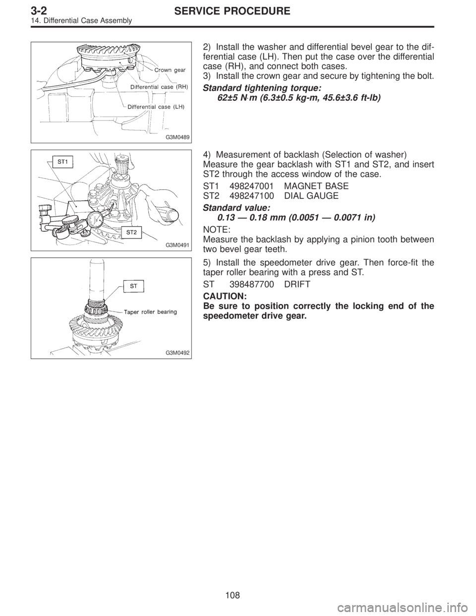
2) Install the washer and differential bevel gear to the dif-
ferential case (LH). Then put the case over the differential
case (RH), and connect both cases.
3) Install the crown gear and secure by tightening the bolt.
Standard tightening torque:
62±5 N⋅m (6.3±0.5 kg-m, 45.6±3.6 ft-lb)
G3M0491
4) Measurement of backlash (Selection of washer)
Measure the gear backlash with ST1 and ST2, and insert
ST2 through the access window of the case.
ST1 498247001 MAGNET BASE
ST2 498247100 DIAL GAUGE
Standard value:
0.13—0.18 mm (0.0051—0.0071 in)
NOTE:
Measure the backlash by applying a pinion tooth between
two bevel gear teeth.
G3M0492
5) Install the speedometer drive gear. Then force-fit the
taper roller bearing with a press and ST.
ST 398487700 DRIFT
CAUTION:
Be sure to position correctly the locking end of the
speedometer drive gear.
108
3-2SERVICE PROCEDURE
14. Differential Case Assembly
Page 1394 of 2890
G4M0604
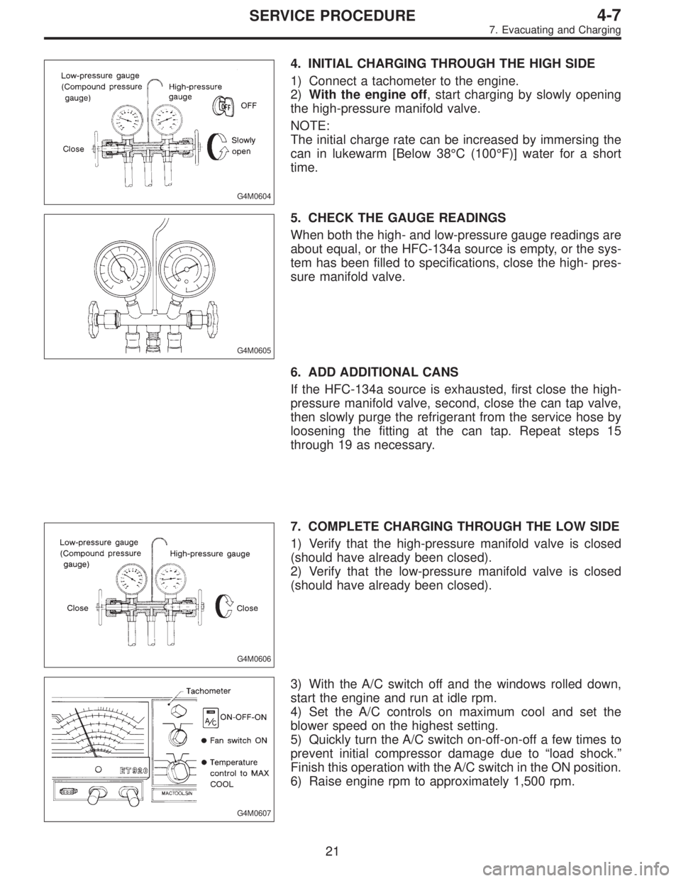
4. INITIAL CHARGING THROUGH THE HIGH SIDE
1) Connect a tachometer to the engine.
2)With the engine off, start charging by slowly opening
the high-pressure manifold valve.
NOTE:
The initial charge rate can be increased by immersing the
can in lukewarm [Below 38°C (100°F)] water for a short
time.
G4M0605
5. CHECK THE GAUGE READINGS
When both the high- and low-pressure gauge readings are
about equal, or the HFC-134a source is empty, or the sys-
tem has been filled to specifications, close the high- pres-
sure manifold valve.
6. ADD ADDITIONAL CANS
If the HFC-134a source is exhausted, first close the high-
pressure manifold valve, second, close the can tap valve,
then slowly purge the refrigerant from the service hose by
loosening the fitting at the can tap. Repeat steps 15
through 19 as necessary.
G4M0606
7. COMPLETE CHARGING THROUGH THE LOW SIDE
1) Verify that the high-pressure manifold valve is closed
(should have already been closed).
2) Verify that the low-pressure manifold valve is closed
(should have already been closed).
G4M0607
3) With the A/C switch off and the windows rolled down,
start the engine and run at idle rpm.
4) Set the A/C controls on maximum cool and set the
blower speed on the highest setting.
5) Quickly turn the A/C switch on-off-on-off a few times to
prevent initial compressor damage due to“load shock.”
Finish this operation with the A/C switch in the ON position.
6) Raise engine rpm to approximately 1,500 rpm.
21
4-7SERVICE PROCEDURE
7. Evacuating and Charging
Page 1402 of 2890
10. Performance Test
1. VEHICLE SET UP
In order to obtain meaningful test results, the vehicle must
be set up to meet the following conditions:
1) Vehicle in shade
2) No wind
3) All vehicle doors closed
4) Front windows opened
5) Hood opened
6) Engine speed set at 1,500 rpm.
7) A/C ON
8) Temperature control lever—Maximum cold
9) Air source—Recirculation
10) Blower speed—4th position (High)
11) Operate A/C for 10 minutes (Minimum) before taking
measurement.
2. MEASUREMENTS
After 10 minutes (Minimum) of A/C operation and using
accurate test equipment, take the following measurements
(in order):
1) Evaporator intake air temperature at recirculation door.
2) Evaporator discharge air temperature at center grill.
3) Condenser (Ambient) intake air temperature measured
0.9 m (3 ft) in front and in line with the center of the con-
denser.
4) Suction (Low) side pressure
5) Discharge (High) side pressure
NOTE:
If only one thermometer is available; 1) take the ambient
measurement first; then 2) the intake air; and 3) dis-
charge air temperature.
28
4-7SERVICE PROCEDURE
10. Performance Test