Page 1447 of 2890
3. FRONT WINDSHIELD AND REAR WINDOW
B5M0254A
Unit: mm (in)
18
5-1SERVICE DATA
3. Datum Dimensions
Page 1507 of 2890
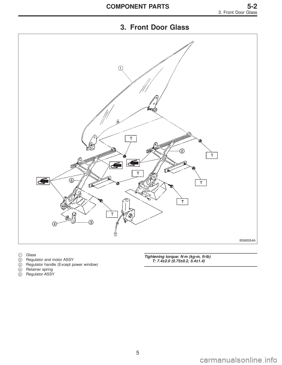
3. Front Door Glass
B5M0054A
�1Glass
�
2Regulator and motor ASSY
�
3Regulator handle (Except power window)
�
4Retainer spring
�
5Regulator ASSY
Tightening torque: N⋅m (kg-m, ft-lb)
T: 7.4±2.0 (0.75±0.2, 5.4±1.4)
5
5-2COMPONENT PARTS
3. Front Door Glass
Page 1508 of 2890
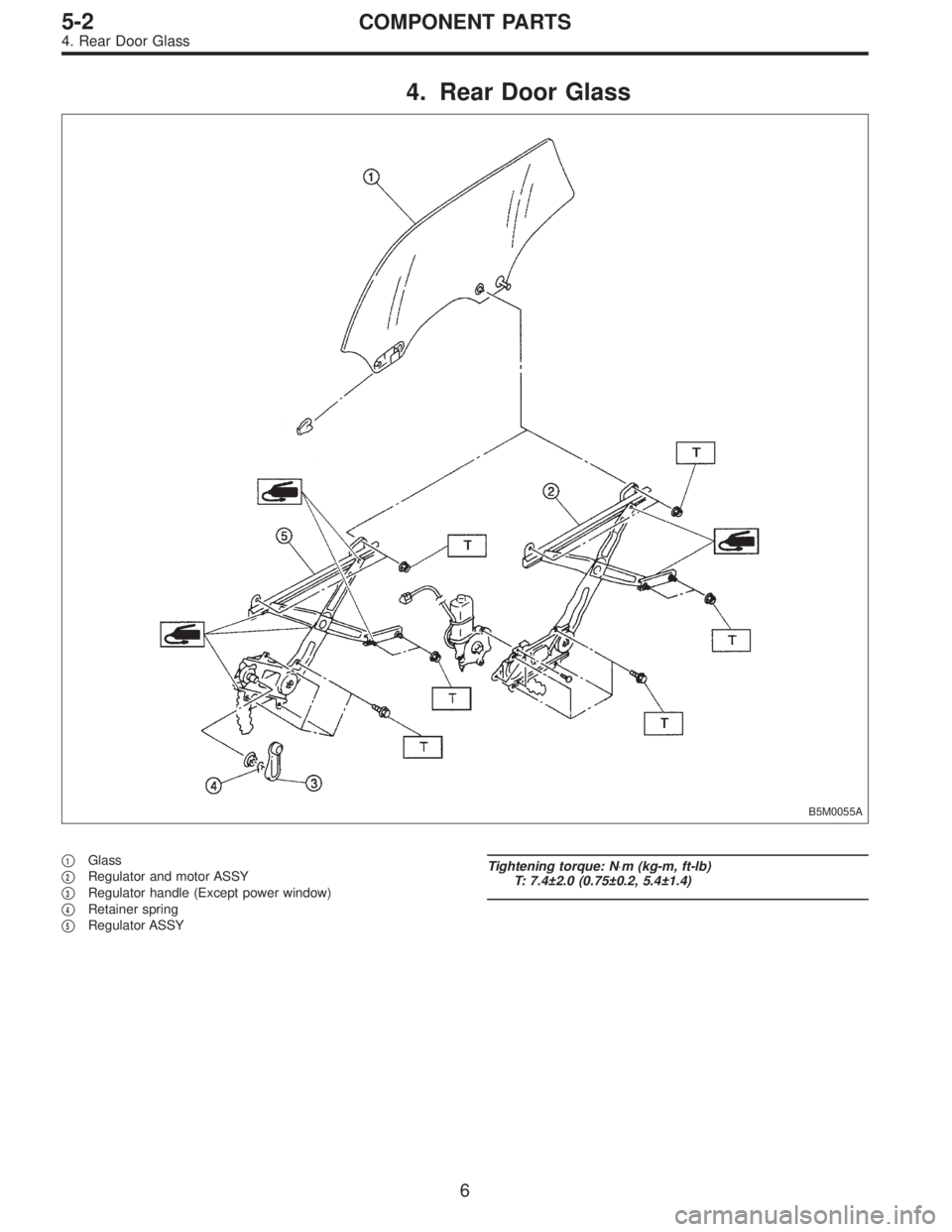
4. Rear Door Glass
B5M0055A
�1Glass
�
2Regulator and motor ASSY
�
3Regulator handle (Except power window)
�
4Retainer spring
�
5Regulator ASSY
Tightening torque: N⋅m (kg-m, ft-lb)
T: 7.4±2.0 (0.75±0.2, 5.4±1.4)
6
5-2COMPONENT PARTS
4. Rear Door Glass
Page 1515 of 2890
G5M0486
2. Door
A: REMOVAL AND INSTALLATION
1. DOOR ASSY
1) Remove lower trim and disconnect connectors from
body harness.
2) Place a cloth or a wood block under door to prevent
damage, and support it with a jack.
3) Remove checker pin by driving it upward. Be careful not
to damage door and body.
G5M0385
4) Remove bolts (M8) securing upper and lower hinges to
door, and remove door from hinges.
Tightening torque:
25±3 N⋅m (2.5±0.3 kg-m, 18.1±2.2 ft-lb)
5) Remove hinges by loosening hinges mounting bolt (M8)
off of body.
Tightening torque:
29±5 N⋅m (3.0±0.5 kg-m, 21.7±3.6 ft-lb)
CAUTION:
Work carefully to avoid damaging door.
6) Installation is in the reverse order of removal.
NOTE:
Apply grease to moving parts of door hinges.
B5M0329A
2. TRIM PANEL
1) Press retainer spring�
1with a thin flat bladed screw-
driver and then remove regulator handle�
2. (models with-
out power window)
B5M0061A
2) Remove gusset cover�1and three screws.
13
5-2SERVICE PROCEDURE
2. Door
Page 1516 of 2890
 Using ST, disengage the clip.
ST 925580000 PULLER
4) Remove trim panel and then disconnect connector.
(models with power window)
CAUTION:
Be careful not to break clip by applying undue forc")
G5M0390
3) Using ST, disengage the clip.
ST 925580000 PULLER
4) Remove trim panel and then disconnect connector.
(models with power window)
CAUTION:
Be careful not to break clip by applying undue force.
Installation is in the reverse order of removal.
G5M0391
3. SEALING COVER
1) Remove trim panel.
2) Remove speaker, remote assembly and disconnect
connectors.
3) Remove sealer with a spatula.
CAUTION:
Be careful because cover may break if sealer is
removed forcefully.
4) Install in reverse order of removal. Some special items
will be described below.
5) Confirm that sealer is properly applied without breaks.
Then install sealing cover.
6) When repairing or replacing sealing cover, use “CEME-
DINE 5430L” as sealer. It may be overlaid on existing
sealer.
Sealer:
CEMEDINE 5430L
B5M0062A
CAUTION:
�Any breaks in sealer can cause water leakage or
entry of air and dust. Be sure sealer is applied in a
continuous line.
�Do not stop up drain hole�
1with sealer.
�Do not stop up install hole�
2with sealing cover.
�Make sure sealing cover bonded areas are free from
wrinkles or openings.
14
5-2SERVICE PROCEDURE
2. Door
Page 1517 of 2890
G5M0392
4. CHECKER
1) Remove trim panel.
2) Remove sealing cover.
3) Apply a cloth to door and body to prevent damaging
them, and remove checker pin by driving it upward.
CAUTION:
Be careful not to damage door and body.
4) Completely close door glass.
5) Loosen two nuts securing checker, and take out
checker through access hole in underside.
Installation should be made in the reverse order of
removal.
Tightening torque:
7.4±2.0 N⋅m (0.75±0.2 kg-m, 5.4±1.4 ft-lb)
5. DOOR GLASS
1) Remove trim panel.
2) Remove sealing cover.
3) Disconnect door mirror connector and then remove
gusset�
1.
4) Remove inner remote.
B5M0063A
5) Remove inner stabilizer�1.
B5M0064A
6) Remove nut and then separate glass holder�1from
guide channel A�
2.
NOTE:
When removing nut, move door window lower glass con-
necting section to service hole of door panel.
7) Remove window glass upward.
CAUTION:
After removing window glass, do not move regulator.
15
5-2SERVICE PROCEDURE
2. Door
Page 1520 of 2890
B5M0068
8. OUTER HANDLE
1) Remove trim panel.
2) Remove sealing cover.
3) Detach door latch rod from outer handle and key lock.
4) Loosen nut securing outer handle and then remove
outer handle from outside.
CAUTION:
Be careful not to damage door.
Installation is in the reverse order of removal.
Tightening torque:
7.4±2.0 N⋅m (0.75±0.2 kg-m, 5.4±1.4 ft-lb)
B5M0069A
9. KEY LOCK
1) Remove trim panel.
2) Remove sealing cover.
3) Completely close door glass.
4) Remove outer handle.
5) Loosen spring�
1securing key lock.
6) Remove key lock from outer handle.
Installation is in the reverse order of removal.
NOTE:
Install so that key slot in key lock comes to center of hole
in outer handle.
B5M0070A
10. GUSSET
NOTE:
Be sure window is all the way down.
1) Remove trim panel.
2) Remove door rearview mirror.
3) Remove sealing cover.
4) Remove bolts and nuts which secure gusset.
5) Lift out gusset�
1.
To install, reverse the above removal procedures.
18
5-2SERVICE PROCEDURE
2. Door
Page 1522 of 2890
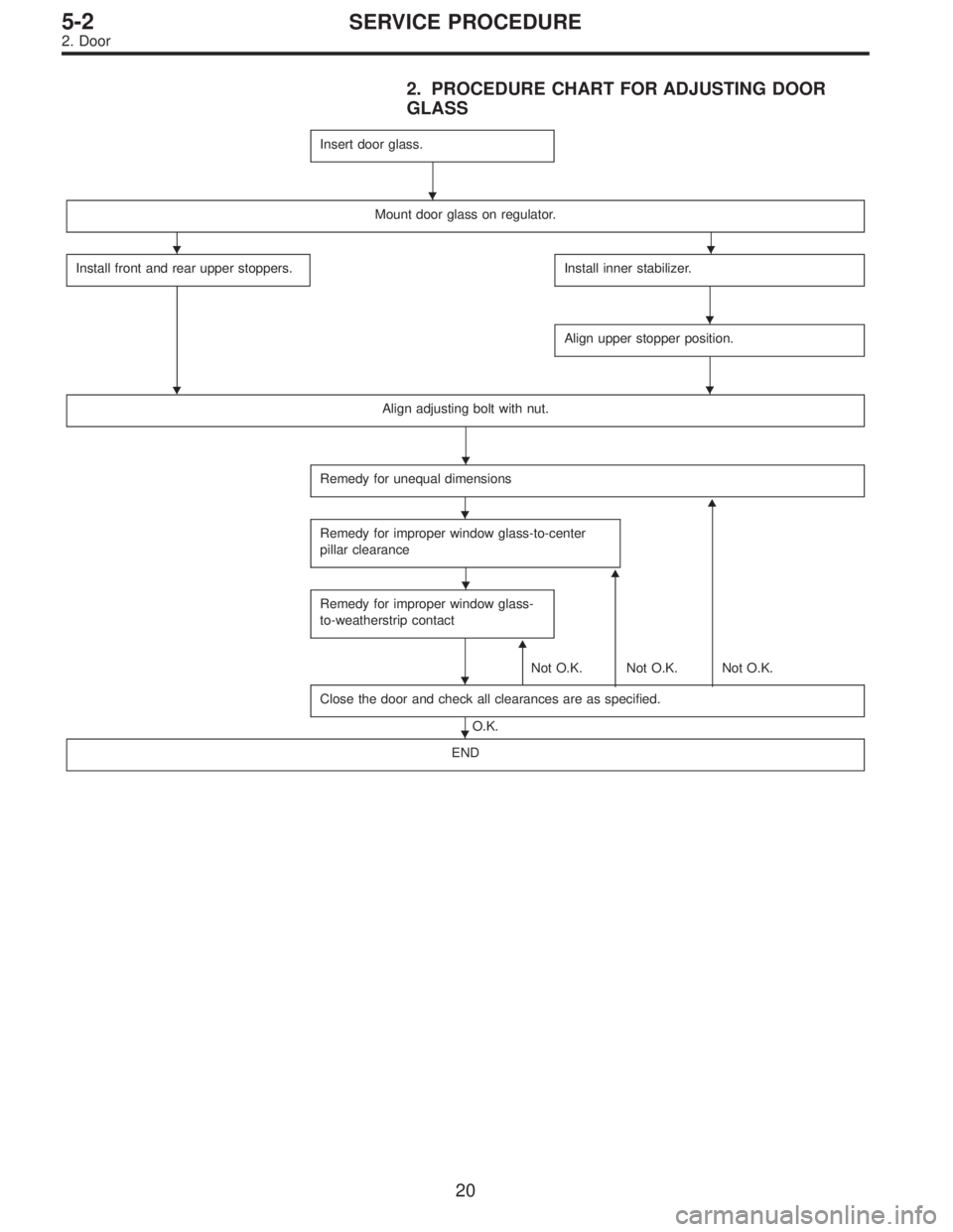
2. PROCEDURE CHART FOR ADJUSTING DOOR
GLASS
Insert door glass.
Mount door glass on regulator.
Install front and rear upper stoppers.
�
Install inner stabilizer.
Align upper stopper position.
Align adjusting bolt with nut.
Remedy for unequal dimensions
�
Remedy for improper window glass-to-center
pillar clearance
�
Remedy for improper window glass-
to-weatherstrip contact
�
Not O.K. Not O.K. Not O.K.
Close the door and check all clearances are as specified.
O.K.
END
�
��
�
�
�
�
�
�
�
20
5-2SERVICE PROCEDURE
2. Door

18
5-1SERVICE DATA
3. Datum Dimensions")
 Remove lower trim and disconnect connectors from
body harness.
2) Place a cloth or a wood block under door to prevent
damage, and support it")
![SUBARU LEGACY 1996 Service Repair Manual G5M0392
4. CHECKER
1) Remove trim panel. <Ref. to 5-2 [W2A2].>
2) Remove sealing cover. <Ref. to 5-2 [W2A3].>
3) Apply a cloth to door and body to prevent damaging
them, and remove checker pin by driv](/manual-img/17/57433/w960_57433-1516.png "SUBARU LEGACY 1996 Service Repair Manual G5M0392
4. CHECKER
1) Remove trim panel. <Ref. to 5-2 [W2A2].>
2) Remove sealing cover. <Ref. to 5-2 [W2A3].>
3) Apply a cloth to door and body to prevent damaging
them, and remove checker pin by driv")
![SUBARU LEGACY 1996 Service Repair Manual B5M0068
8. OUTER HANDLE
1) Remove trim panel. <Ref. to 5-2 [W2A2].>
2) Remove sealing cover. <Ref. to 5-2 [W2A3].>
3) Detach door latch rod from outer handle and key lock.
4) Loosen nut securing outer](/manual-img/17/57433/w960_57433-1519.png "SUBARU LEGACY 1996 Service Repair Manual B5M0068
8. OUTER HANDLE
1) Remove trim panel. <Ref. to 5-2 [W2A2].>
2) Remove sealing cover. <Ref. to 5-2 [W2A3].>
3) Detach door latch rod from outer handle and key lock.
4) Loosen nut securing outer")