Page 1542 of 2890
 Glass runs out of weatherstrip lip when considerable hand
pressure is applied to it from inside.
G5M0502(This conditi")
1. Door Glass
Condition Apparent cause/Correction
Glass in fully closed
position1) Glass runs out of weatherstrip lip when considerable hand
pressure is applied to it from inside.
G5M0502(This condition may cause wind/booming noise during high-
speed operation.)�Insufficient upward travel of glass
Increase upward travel of glass.
2) Clearance exists between glass and weatherstrip when light
hand pressure is applied to it at center and rear pillar
locations.
G5M0503(This condition may cause wind noise and/or water leakage.)�Insufficient glass-to-door
weatherstrip contact
Check stabilizer and glass for
proper contact. Increase contact
using upper sash adjustment bolt.
�Improper adjustment of striker in
in-out direction
Close door and check for alignment
of striker with vehicle body.
3) Adjust door glass so that it is aligned with door rearview
mirror gusset.
G5M0504
�Window is not properly adjusted in
up-down/fore-aft direction.
Adjust window. If necessary, move
B channel regulator to eliminate
window tilt.
�Gusset is not properly adjusted in
fore-aft direction.
Adjust gusset after loosing all bolts
and nuts witch tightening it.
39
5-2DIAGNOSTICS
1. Door Glass
Page 1543 of 2890
 Glass rides over weatherstrip lip when door is closed.
G5M0505(This condition increases wind/booming noise, leakage and/or
eff")
Condition Apparent cause/Correction
Door in fully closed/
open position1) Glass rides over weatherstrip lip when door is closed.
G5M0505(This condition increases wind/booming noise, leakage and/or
effort required to close door.)�Improper up-down and in-out glass
alignments
Adjust glass for up-down and in-out
alignments (incl. rear sash, upper
stopper adjustment, etc.). If
necessary, correct glass tilt by
moving B channel regulator.
2) Edge of glass contacts retainer when door is fully closed.
G5M0506
�Improper glass-to-center pillar
weatherstrip or excessive glass
contact to weatherstrip
�Excessive adjusting in contact to
weatherstrip
Causes rear edge of glass to tilt
inboard closer to center pillar.
Adjust rear sash adjustment bolt to
reduce glass contact to
weatherstrip.
Raise or lower
window glass1) Considerable effort or time is required to operate regulator.
Standard operating effort:
�Entire up-down travel except for point 5 mm (0.20 in)
below fully closed position:
29.4 N (3.0 kg, 6.6 lb)
�Point 5 mm (0.20 in) below fully closed position:
44.1 N (4.5 kg, 9.9 lb)
G5M0507
�Sliding resistance increased due to
high stabilizer-to-glass contact
pressure.
Reduce contact by mounting inner
stabilizer to inside of the vehicle.
�High glass-to-windshield contact
pressure
Reduce contact using upper sash
adjustment bolt.
�Unequal contact adjustment stroke
between front and rear sashes
Set to equal stroke.
�Tilt of rear sash adjustment bolt
mounting bracket
Correct tilt of bracket so it is
parallel to inner panel.
40
5-2DIAGNOSTICS
1. Door Glass
Page 1544 of 2890
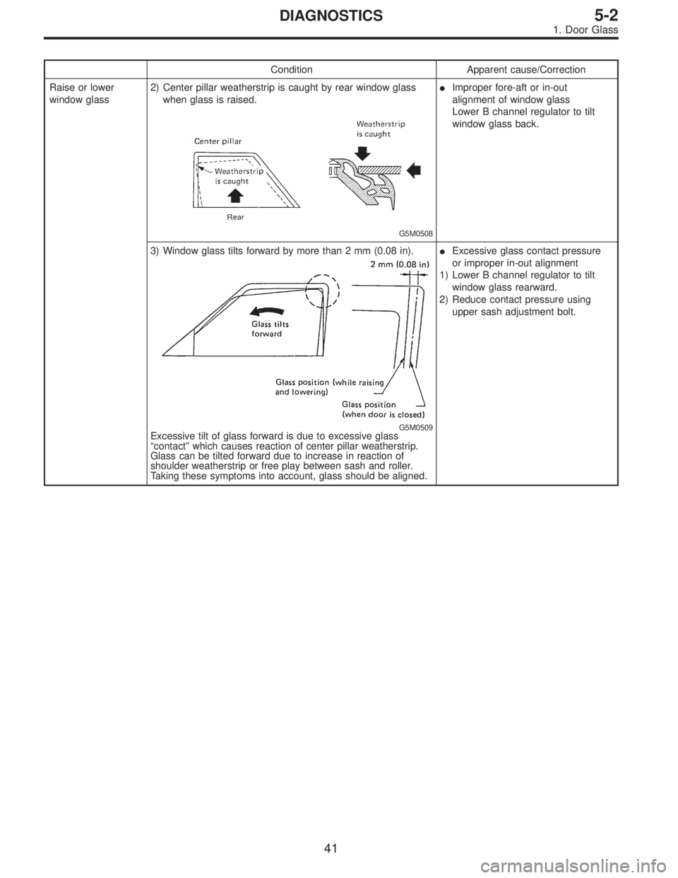
Condition Apparent cause/Correction
Raise or lower
window glass2) Center pillar weatherstrip is caught by rear window glass
when glass is raised.
G5M0508
�Improper fore-aft or in-out
alignment of window glass
Lower B channel regulator to tilt
window glass back.
3) Window glass tilts forward by more than 2 mm (0.08 in).
G5M0509Excessive tilt of glass forward is due to excessive glass
“contact”which causes reaction of center pillar weatherstrip.
Glass can be tilted forward due to increase in reaction of
shoulder weatherstrip or free play between sash and roller.
Taking these symptoms into account, glass should be aligned.�Excessive glass contact pressure
or improper in-out alignment
1) Lower B channel regulator to tilt
window glass rearward.
2) Reduce contact pressure using
upper sash adjustment bolt.
41
5-2DIAGNOSTICS
1. Door Glass
Page 1656 of 2890
Front wiper
motorInput 12 V—54 W or less
Rear wiper motor Input 12 V—42 W or less
Front washer
motorPump type Centrifugal
Input 12 V—36 W or less
Rear washer
motorPump type Centrifugal
Input 12 V—36 W or less
Horn12 V—350 Hz
Cigarette lighter Input 12 V—120 W
Rear window
defoggerInput 12 V—160 W
Indicator light 12 V—50 mA
3
6-2SPECIFICATIONS
1. Body Electrical
Page 1685 of 2890
B6M0165
3) Check wiper motor for proper stoppage.
Connect battery to wiper motor. After operating wiper motor
at low speed, disconnect battery to stop it.
B6M0166
4) Reconnect battery and ensure that wiper motor stops at
“AUTO STOP”after operating at low speed.
B6M0111
3. WASHER MOTOR
Apply battery voltage between terminals of washer motor
connector and check that washer motor operates.
G6M0126
11. Rear Wiper and Washer
A: ON-CAR SERVICES
1. ADJUSTMENT
1) Adjust wiper blade in original position as shown in fig-
ure by changing wiper arm installation.
Original position:
A: 25—35 mm (0.98—1.38 in)
G6M0127
2) Adjust washer ejecting point on rear gate window as
shown in figure when the vehicle stops.
Ejecting point:
A: 25 mm (0.98 in)
B: 200—300 mm (7.87—11.81 in)
27
6-2SERVICE PROCEDURE
10. Front Wiper and Washer - 11. Rear Wiper and Washer
Page 1686 of 2890
B6M0165
3) Check wiper motor for proper stoppage.
Connect battery to wiper motor. After operating wiper motor
at low speed, disconnect battery to stop it.
B6M0166
4) Reconnect battery and ensure that wiper motor stops at
“AUTO STOP”after operating at low speed.
B6M0111
3. WASHER MOTOR
Apply battery voltage between terminals of washer motor
connector and check that washer motor operates.
G6M0126
11. Rear Wiper and Washer
A: ON-CAR SERVICES
1. ADJUSTMENT
1) Adjust wiper blade in original position as shown in fig-
ure by changing wiper arm installation.
Original position:
A: 25—35 mm (0.98—1.38 in)
G6M0127
2) Adjust washer ejecting point on rear gate window as
shown in figure when the vehicle stops.
Ejecting point:
A: 25 mm (0.98 in)
B: 200—300 mm (7.87—11.81 in)
27
6-2SERVICE PROCEDURE
10. Front Wiper and Washer - 11. Rear Wiper and Washer
Page 1690 of 2890
 Connect battery to terminal No. 1 and ground terminal
No. 2.
2) Check continuity between terminals as indicated in
table below:
When current flows. Between terminals
No.")
G6M0134
3. REAR WIPER RELAY
1) Connect battery to terminal No. 1 and ground terminal
No. 2.
2) Check continuity between terminals as indicated in
table below:
When current flows. Between terminals
No. 3 and No. 5Continuity does not
exist.
Between terminals
No. 3 and No. 4Continuity exists.
When current does not flow. Between terminals
No. 3 and No. 5Continuity exists.
Between terminals
No. 3 and No. 4Continuity does not
exist.
Between terminals
No. 1 and No. 2Continuity exists.
B6M0111
4. WASHER MOTOR
Apply battery voltage between terminals of washer motor
connector and check that washer motor operates.
12. Rear Window Defogger
A: REMOVAL AND INSTALLATION
1. DEFOGGER SWITCH
1) Remove screws which secure meter visor.
2) Remove meter visor from instrument panel while dis-
connecting connectors.
3) Remove rear window defogger switch from meter visor.
B6M0119
B: INSPECTION
1. DEFOGGER SWITCH
Move rear window defogger switch to each position and
check continuity between terminals as indicated in table
below:
Terminal
Switch position35 14 2
OFF�
�
ON�����
31
6-2SERVICE PROCEDURE
11. Rear Wiper and Washer - 12. Rear Window Defogger
Page 1691 of 2890
 Connect battery to terminal No. 1 and ground terminal
No. 2.
2) Check continuity between terminals as indicated in
table below:
When current flows. Between terminals
No.")
G6M0134
3. REAR WIPER RELAY
1) Connect battery to terminal No. 1 and ground terminal
No. 2.
2) Check continuity between terminals as indicated in
table below:
When current flows. Between terminals
No. 3 and No. 5Continuity does not
exist.
Between terminals
No. 3 and No. 4Continuity exists.
When current does not flow. Between terminals
No. 3 and No. 5Continuity exists.
Between terminals
No. 3 and No. 4Continuity does not
exist.
Between terminals
No. 1 and No. 2Continuity exists.
B6M0111
4. WASHER MOTOR
Apply battery voltage between terminals of washer motor
connector and check that washer motor operates.
12. Rear Window Defogger
A: REMOVAL AND INSTALLATION
1. DEFOGGER SWITCH
1) Remove screws which secure meter visor.
2) Remove meter visor from instrument panel while dis-
connecting connectors.
3) Remove rear window defogger switch from meter visor.
B6M0119
B: INSPECTION
1. DEFOGGER SWITCH
Move rear window defogger switch to each position and
check continuity between terminals as indicated in table
below:
Terminal
Switch position35 14 2
OFF�
�
ON�����
31
6-2SERVICE PROCEDURE
11. Rear Wiper and Washer - 12. Rear Window Defogger

 Check wiper motor for proper stoppage.
Connect battery to wiper motor. After operating wiper motor
at low speed, disconnect battery to stop it.
B6M0166
4) Reconnect battery and ensure that")
 Check wiper motor for proper stoppage.
Connect battery to wiper motor. After operating wiper motor
at low speed, disconnect battery to stop it.
B6M0166
4) Reconnect battery and ensure that")