Page 1300 of 2890
B4M0622A
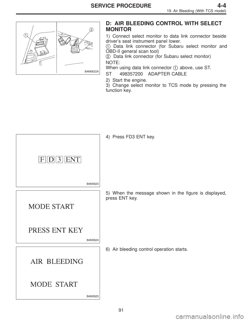
D: AIR BLEEDING CONTROL WITH SELECT
MONITOR
1) Connect select monitor to data link connector beside
driver’s seat instrument panel lower.
�
1Data link connector (for Subaru select monitor and
OBD-II general scan tool)
�
2Data link connector (for Subaru select monitor)
NOTE:
When using data link connector�
1above, use ST.
ST 498357200 ADAPTER CABLE
2) Start the engine.
3) Change select monitor to TCS mode by pressing the
function key.
B4M0623
4) Press FD3 ENT key.
B4M0624
5) When the message shown in the figure is displayed,
press ENT key.
B4M0625
6) Air bleeding control operation starts.
91
4-4SERVICE PROCEDURE
19. Air Bleeding (With TCS model)
Page 1301 of 2890
B4M0626
7) Select monitor indicates that air bleeding control is now
operating.
B4M0627
8) When air bleeding control cannot be started (by system
malfunction, etc.), the message shown in the figure will be
displayed.
NOTE:
Read the trouble codes. Repair faulty parts.
92
4-4SERVICE PROCEDURE
19. Air Bleeding (With TCS model)
Page 1307 of 2890
B4M0635
4) Press FD1 ENT key.
B4M0634
5) The message shown in the figure is displayed as fol-
lows:
(1) When using the brake tester, depress brake pedal
with braking force of 981 to 1,471 N (100 to 150 kg, 221
to 331 lb).
(2) When using the pressure gauge, depress brake
pedal so as to make the pressure gauge indicate 3,432
kPa (35 kg/cm
2, 498 psi)
B4M0624
6) When the message shown in the figure is displayed,
press ENT key.
7) Checked portions will be displayed on select monitor.
B4M0627
8) When ABS sequence control cannot be started (by sys-
tem malfunction, etc.), the message shown in the figure will
be displayed.
NOTE:
Read the trouble codes. Repair faulty parts.
9) After completion of ABS sequence control, turn ignition
switch OFF.
98
4-4SERVICE PROCEDURE
20. Hydraulic Unit for ABS/TCS System
Page 1313 of 2890
2. OPERATIONAL GUIDELINES OF THE TCS
SEQUENCE CONTROL WITH SELECT MONITOR
1) Connect select monitor to data link connector beside
driver’s seat heater unit.
2) Engine starts.
3) Put select monitor to TCS mode.
4) Put select monitor to FBI mode. Make sure code 11 is
indicated.
NOTE:
When trouble codes are stored in memory, repair the faulty
parts.
B4M0639
5) Press FD2 ENT key.
B4M0624
6) When the message shown in the figure is displayed,
press ENT key.
7) Checked portions will be displayed on select monitor.
B4M0627
8) When TCS sequence control cannot be started (by sys-
tem malfunction, etc.), the message shown in the figure will
be displayed.
NOTE:
Read the trouble codes. Repair faulty parts.
104
4-4SERVICE PROCEDURE
20. Hydraulic Unit for ABS/TCS System
Page 1325 of 2890
B4M0997
5) The message shown in the figure is displayed.
B4M0998
6) The message shown in the figure is displayed as fol-
lows:
(1) When using the brake tester, depress brake pedal
with braking force of 981 N (100 kg, 221 lb).
(2) When using the pressure gauge, depress brake
pedal so as to make the pressure gauge indicate 3,432
kPa (35 kg/cm
2, 498 psi).
CAUTION:
Do not depress the clutch pedal.
B4M0999
7) When the message shown in the figure is displayed,
press ENT key.
8) Check points will be displayed on select monitor.
B4M1000
9) When ABS sequence control cannot be started (by sys-
tem malfunction, etc.), the message shown in the figure will
be displayed.
NOTE:
Read the trouble codes. Repair faulty parts.
B4M1030
10) After completion of ABS sequence control, turn ignition
switch OFF.
11 5
4-4SERVICE PROCEDURE
22. Hydraulic Unit for ABS System (ABS 5.3 Type)
Page 1334 of 2890
B4M0918A
: Connector & terminal
(P9) No. 2 (+)—No.1(�)
Is voltage 0.7±0.2 V when G sensor is
inclined backwards to 90°?
: G sensor is normal.
: Replace G sensor.
2. USING SELECT MONITOR
1) Turn ignition switch to OFF.
2) Connect select monitor connector to data link connec-
tor.
3) Turn select monitor into ABS mode.
B4M0927
4) Press F,1and 0on the select monitor.
5) Read the select monitor display.
: Is the indicated reading 2.3±0.2 V when the
vehicle is in horizontal position?
: Go to next step 6).
: Replace G sensor.
6) Remove console box.
7) Remove G sensor from vehicle. (Do not disconnect
connector.)
B4M0917A
8) Read the select monitor display.
: Is the indicated reading 3.9±0.2 V when G
sensor is inclined forwards to 90°?
: Go to next.
: Replace G sensor.
B4M0918A
: Is the indicated reading 0.7±0.2 V when G
sensor is inclined backwards to 90°?
: G sensor is normal.
: Replace G sensor.
123
4-4SERVICE PROCEDURE
24. G Sensor for ABS System (ABS 5.3 Type)
Page 1387 of 2890
Tools and Equipment Description
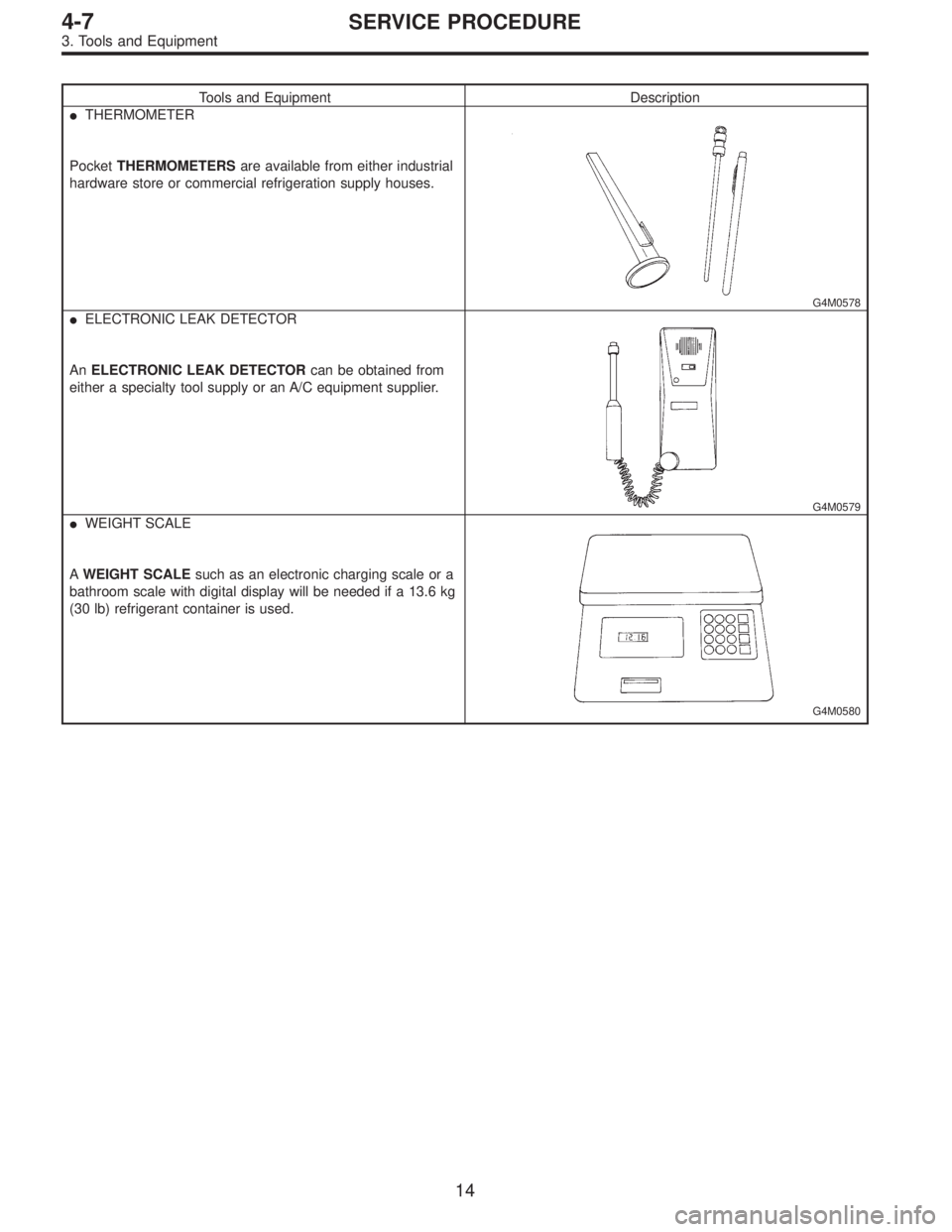
�THERMOMETER
PocketTHERMOMETERSare available from either industrial
hardware store or commercial refrigeration supply houses.
G4M0578
�ELECTRONIC LEAK DETECTOR
AnELECTRONIC LEAK DETECTORcan be obtained from
either a specialty tool supply or an A/C equipment supplier.
G4M0579
�WEIGHT SCALE
AWEIGHT SCALEsuch as an electronic charging scale or a
bathroom scale with digital display will be needed if a 13.6 kg
(30 lb) refrigerant container is used.
G4M0580
14
4-7SERVICE PROCEDURE
3. Tools and Equipment
Page 1801 of 2890
OBD0060
5) Turn ignition switch to ON (engine OFF) and Subaru
select monitor switch to ON.
6) Using Subaru select monitor, call up diagnostic trouble
code(s) and various data, then record them.
H2M1149
2. READ DIAGNOSTIC TROUBLE CODE (DTC)
SHOWN ON DISPLAY. (MODE FB1)
1) Select engine mode using function key.
Press the function key [0].
G3M0152
2) Designate mode using function key.
Press [F] [B] [1] [ENT] in that order.
OBD0062
3) Ensure diagnostic trouble code(s) is shown.
(1) When there is only one diagnostic trouble code.
OBD0063
(2) When there are multiple diagnostic trouble codes.
NOTE:
For details concerning diagnostic trouble codes, refer to
the DIAGNOSTIC TROUBLE CODE (DTC) LIST, 2-7
[T10A0].
33
2-7ON-BOARD DIAGNOSTICS II SYSTEM
3. Diagnosis System
 Select monitor indicates that air bleeding control is now
operating.
B4M0627
8) When air bleeding control cannot be started (by system
malfunction, etc.), the message shown in the figure wi")
 Press FD1 ENT key.
B4M0634
5) The message shown in the figure is displayed as fol-
lows:
(1) When using the brake tester, depress brake pedal
with braking force of 981 to 1,471 N (100 to 15")
![SUBARU LEGACY 1996 Service Repair Manual 2. OPERATIONAL GUIDELINES OF THE TCS
SEQUENCE CONTROL WITH SELECT MONITOR
1) Connect select monitor to data link connector beside
driver’s seat heater unit. <Ref. to [W19D0] step 1).>
2) Engine star](/manual-img/17/57433/w960_57433-1312.png "SUBARU LEGACY 1996 Service Repair Manual 2. OPERATIONAL GUIDELINES OF THE TCS
SEQUENCE CONTROL WITH SELECT MONITOR
1) Connect select monitor to data link connector beside
driver’s seat heater unit. <Ref. to [W19D0] step 1).>
2) Engine star")
 The message shown in the figure is displayed.
B4M0998
6) The message shown in the figure is displayed as fol-
lows:
(1) When using the brake tester, depress brake pedal
with braking force o")
 No. 2 (+)—No.1(�)
Is voltage 0.7±0.2 V when G sensor is
inclined backwards to 90°?
: G sensor is normal.
: Replace G sensor.
2. USING SELECT MONITOR
1) Turn ig")
 Turn ignition switch to ON (engine OFF) and Subaru
select monitor switch to ON.
6) Using Subaru select monitor, call up diagnostic trouble
code(s) and various data, then record them.
H2M114")