Page 1825 of 2890
H2M1149
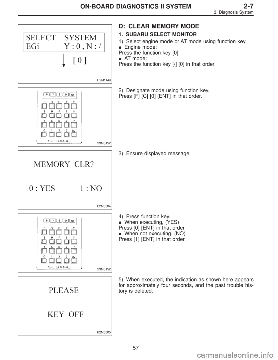
D: CLEAR MEMORY MODE
1. SUBARU SELECT MONITOR
1) Select engine mode or AT mode using function key.
�Engine mode:
Press the function key [0].
�AT mode:
Press the function key [/] [0] in that order.
G3M0152
2) Designate mode using function key.
Press [F] [C] [0] [ENT] in that order.
B2M0504
3) Ensure displayed message.
G3M0152
4) Press function key.
�When executing, (YES)
Press [0] [ENT] in that order.
�When not executing, (NO)
Press [1] [ENT] in that order.
B2M0505
5) When executed, the indication as shown here appears
for approximately four seconds, and the past trouble his-
tory is deleted.
57
2-7ON-BOARD DIAGNOSTICS II SYSTEM
3. Diagnosis System
Page 1826 of 2890
 After the display is gone, turn Subaru select monitor
switch and ignition switch to OFF.
NOTE:
When the ECM, battery terminals, etc. are disconnected
after memory is cleared, idling speed m")
G3M0151
6) After the display is gone, turn Subaru select monitor
switch and ignition switch to OFF.
NOTE:
When the ECM, battery terminals, etc. are disconnected
after memory is cleared, idling speed may increase. This is
not considered a problem because the ISC valve duty con-
trolled learning value has been cleared. To return the
engine to idling speed, idle for approximately 2 minutes
with air conditioner off.
2. OBD-II GENERAL SCAN TOOL
For clear memory procedures using the OBD-II general
scan tool, refer to the OBD-II General Scan Tool Instruction
Manual.
OBD0072A
E: INSPECTION MODE
1. PREPARATIONS FOR THE INSPECTION MODE
Raise the vehicle using a garage jack and place on safety
stands or drive the vehicle onto free rollers.
�FULL-TIME AWD MODELS
WARNING:
�Before raising the vehicle, ensure parking brakes
are applied.
�Do not use a pantograph jack in place of a safety
stand.
�Secure a rope or wire to the front and rear towing or
tie-down hooks to prevent the lateral runout of front
wheels.
�Do not abruptly depress/release clutch pedal or
accelerator pedal during works even when engine is
operating at low speeds since this may cause vehicle
to jump off free rollers.
�In order to prevent the vehicle from slipping due to
vibration, do not place any wooden blocks or similar
items between the safety stands and the vehicle.
58
2-7ON-BOARD DIAGNOSTICS II SYSTEM
3. Diagnosis System
Page 1830 of 2890
 Start the engine.
NOTE:
�Ensure the selector lever is placed in the“P”position
before starting. (AT vehicles)
�Depress clutch pedal when starting the engine. (MT
vehicles)
4) Using the selector")
3) Start the engine.
NOTE:
�Ensure the selector lever is placed in the“P”position
before starting. (AT vehicles)
�Depress clutch pedal when starting the engine. (MT
vehicles)
4) Using the selector lever or shift lever, turn the“P”posi-
tion switch and the“N”position switch to ON.
5) Depress the brake pedal to turn the brake switch ON.
(AT vehicles)
6) Keep engine speed in the 2,500—3,000 rpm range for
40 seconds.
NOTE:
On models without tachometer, use the Subaru select
monitor or tachometer (Secondary pickup type).
7) Place the selector lever or shift lever in the“D”position
(AT vehicles) or“1st”gear (MT vehicles) and drive the
vehicle at 5 to 10 km/h (3 to 6 MPH).
NOTE:
�On AWD vehicles, release the parking brake.
�The speed difference between front and rear wheels
may light either the ABS or the ABS/TCS warning light, but
this indicates no malfunctions. When engine control diag-
nosis is finished, perform the ABS or the ABS/TCS memory
clearance procedure of self-diagnosis system.
4-4b [T6D2] or [T9K0], 4-4c [T6D2] or [T9J0].>
8) Using the OBD-II general scan tool, check for diagnos-
tic trouble code(s) and record the result(s).
NOTE:
�For detailed operation procedures, refer to the OBD-II
General Scan Tool Instruction Manual.
�For details concerning diagnostic trouble codes, refer to
the DIAGNOSTIC TROUBLE CODE (DTC) LIST, 2-7
[T10A0].
H2M1149
4. READ DIAGNOSTIC TROUBLE CODE (DTC)
SHOWN ON DISPLAY. (MODE FB0
MODE>)
Using Subaru select monitor, check for diagnostic trouble
code(s) and record the result(s).
1) Select engine mode using function key.
Press the function key [0].
62
2-7ON-BOARD DIAGNOSTICS II SYSTEM
3. Diagnosis System
Page 1833 of 2890
OBD0060
6) Turn ignition switch to ON (engine OFF) and Subaru
select monitor switch to ON.
H2M1149
7) Select engine mode using function key.
Press the function key [0].
G3M0152
8) Designate mode using function key.
Refer to“6. READ DATA FUNCTION KEY LIST FOR
ENGINE”2-7 [T3C6].
(Example: Press [F] [D] [0] [5] [ENT] in that order.)
B2M0650
9) Ensure displayed message.
B2M0651
10) Press the function key.
(1) When executing, press the function key [0].
65
2-7ON-BOARD DIAGNOSTICS II SYSTEM
3. Diagnosis System
Page 1834 of 2890
B2M0652
NOTE:
When in compulsory valve operation check mode the moni-
tor indicates the execution of valve check on display.
B2M0653
(2) When not executing or stopping the compulsory
valve check mode, press the function key [1].
B2M0643
11) When compulsory valve operation check mode is
exited or check completed, the monitor indicates the
completion of compulsory valve operation check on the
display, and automatically returns to the initial mode
(FUNCTION MODE: F00).
G3M0151
G: FINISHING DIAGNOSIS OPERATION
1. SUBARU SELECT MONITOR
1) Disconnect test mode connector at the lower portion of
instrument panel (on the driver’s side), to the side of the
center console box.
2) Turn Subaru select monitor switch and ignition switch to
OFF.
3) Disconnect Subaru select monitor from its data link con-
nector.
66
2-7ON-BOARD DIAGNOSTICS II SYSTEM
3. Diagnosis System
Page 1838 of 2890
 I/O SIGNAL
OBD0092A
ContentConnector
No.Terminal
No.Signal (V)
Note
Ignition SW ON
(Engine OFF)Engine ON (Idling)
Crankshaft
position
sensorSignal (+)")
5. Specified Data
1. ENGINE CONTROL MODULE (ECM) I/O SIGNAL
OBD0092A
ContentConnector
No.Terminal
No.Signal (V)
Note
Ignition SW ON
(Engine OFF)Engine ON (Idling)
Crankshaft
position
sensorSignal (+) B84 8 0�7—+7 Sensor output waveform
Signal (�) B84 29 0 0—
Shield B84 54 0 0—
Camshaft
position
sensorSignal (+) B84 7 0�7—+7 Sensor output waveform
Signal (�) B84 28 0 0—
Shield B84 54 0 0—
Mass air
flow sensorSignal B84 5 0—0.3 0.8—1.2—
Shield B84 57 0 0—
GND B84 20 0 0—
Throttle
position
sensorSignal B84 6Fully closed: 0.2—1.0
Fully opened: 4.2—4.7—
Power
supplyB84 21 5 5—
GND B84 20 0 0—
Front
oxygen
sensorSignal B84 23 0 0—0.9—
Shield B84 56 0 0—
Rear
oxygen
sensorSignal B84 24 0 0—0.9—
Shield B84 56 0 0—
Engine coolant
temperature sensorB84 22 1.0—1.4 1.0—1.4 After warm-up
Vehicle speed sensor 2 B84 83 0 or 5 0 or 5“5”and“0”are repeatedly
displayed when vehicle is
driven.
Starter switch B84 86 0 0 Cranking: 8 to 14
A/C switch B84 60ON: 10—13
OFF: 0ON: 13—14
OFF: 0—
Ignition switch B84 85 10—13 13—14—
Neutral position switch
(MT)
B84 82ON: 5.0±0.5
OFF: 0�On MT model; switch is ON
when gear is in neutral position.
Neutral position switch
(AT)ON: 0
OFF: 5.0±0.5�On AT model; switch is ON when
shift is in“N”or“P”position.
Test mode connector B84 84 5 5 When connected: 0
70
2-7ON-BOARD DIAGNOSTICS II SYSTEM
5. Specified Data
Page 1843 of 2890
![SUBARU LEGACY 1996 Service Repair Manual 6. Basic Diagnostics Procedure
Trouble occurs.
Ask the customer when and how the
trouble occurred using interview
check list. <Ref. to 2-7 [T602].>
Start the engine.
Ye s�NoInspection using“8. Diagn](/manual-img/17/57433/w960_57433-1842.png "SUBARU LEGACY 1996 Service Repair Manual 6. Basic Diagnostics Procedure
Trouble occurs.
Ask the customer when and how the
trouble occurred using interview
check list. <Ref. to 2-7 [T602].>
Start the engine.
Ye s�NoInspection using“8. Diagn")
6. Basic Diagnostics Procedure
Trouble occurs.
Ask the customer when and how the
trouble occurred using interview
check list.
Start the engine.
Ye s�NoInspection using“8. Diagnostics for
Engine Start Failure 2-7 [T800]”.
Malfunction indicator lamp (MIL) illu-
minates.
Ye s�NoInspection using“9. General Diag-
nostics Table 2-7 [T900]”.
Inspection using Subaru select moni-
tor or OBD-II general scan tool.
(Subaru select monitor: MODE FB1)
Trouble code
�No trouble code designated.Repair.
See NOTE: *1
designated.
Inspection using“10. Diagnostics
Chart with Trouble Code 2-7
[T1000]”.
See NOTE: *2.
�Trouble code
designated.
�
Repair.
Inspection mode
Inspection using Subaru select moni-
tor or OBD-II general scan tool.
(Subaru select monitor: MODE FB0)
No trouble code
�Clear memory mode.�
designated.
END
NOTE:
*1: If trouble code is not shown on display although the
MIL illuminates, perform diagnostics of the MIL (CHECK
ENGINE LIGHT) circuit or combination meter.
Diagnostics for CHECK ENGINE Malfunction Indicator
Lamp (MIL) 2-7 [T700].”>
*2: Carry out the basic check, only when trouble code
about automatic transmission is shown on display.
2-7 [T601].>
�
�
�
�
�
�
75
2-7ON-BOARD DIAGNOSTICS II SYSTEM
6. Basic Diagnostics Procedure
Page 1844 of 2890
1. BASIC CHECK ITEMS FOR AT
When trouble code about automatic transmission is shown
on display, carry out the following basic check. After that,
carry out the replacement or repair work.
1) ATF level check
2) Differential gear oil level check
3) ATF leak check
4) Differential gear oil leak check
5) Brake band adjustment
6) Stall test
7) Line pressure test
8) Transfer clutch pressure test
9) Time lag test
10) Road test
11) Shift characteristics
NOTE:
As for the method, refer to 3-2 [W2A0], [W2B1], [W300].
76
2-7ON-BOARD DIAGNOSTICS II SYSTEM
6. Basic Diagnostics Procedure
![SUBARU LEGACY 1996 Service Repair Manual OBD0060
6) Turn ignition switch to ON (engine OFF) and Subaru
select monitor switch to ON.
H2M1149
7) Select engine mode using function key.
Press the function key [0].
G3M0152
8) Designate mode using](/manual-img/17/57433/w960_57433-1832.png "SUBARU LEGACY 1996 Service Repair Manual OBD0060
6) Turn ignition switch to ON (engine OFF) and Subaru
select monitor switch to ON.
H2M1149
7) Select engine mode using function key.
Press the function key [0].
G3M0152
8) Designate mode using")
 When not executing or stopping the compulsory
valve check mode,")
 ATF level")