Page 1341 of 2890
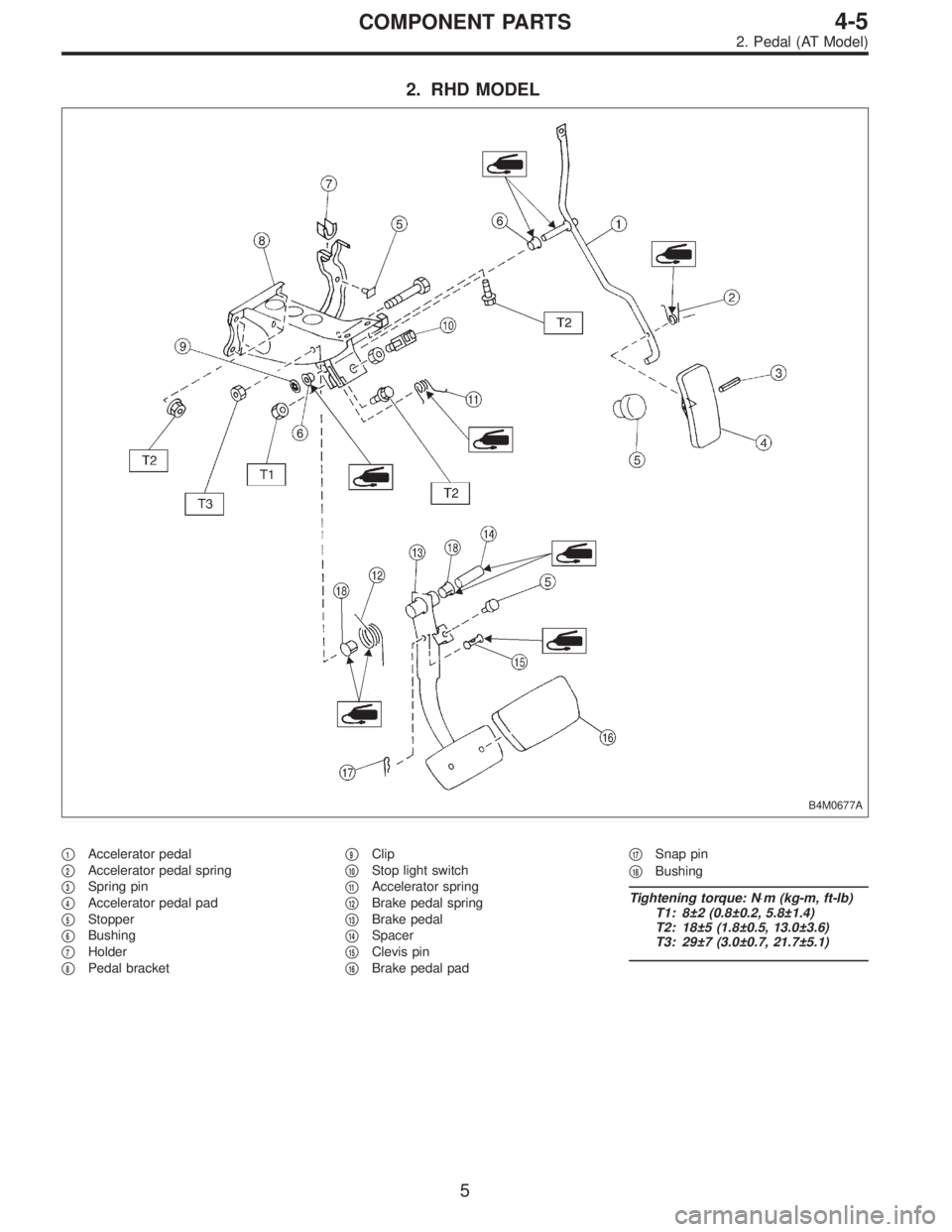
2. RHD MODEL
B4M0677A
�1Accelerator pedal
�
2Accelerator pedal spring
�
3Spring pin
�
4Accelerator pedal pad
�
5Stopper
�
6Bushing
�
7Holder
�
8Pedal bracket�
9Clip
�
10Stop light switch
�
11Accelerator spring
�
12Brake pedal spring
�
13Brake pedal
�
14Spacer
�
15Clevis pin
�
16Brake pedal pad�
17Snap pin
�
18Bushing
Tightening torque: N⋅m (kg-m, ft-lb)
T1: 8±2 (0.8±0.2, 5.8±1.4)
T2: 18±5 (1.8±0.5, 13.0±3.6)
T3: 29±7 (3.0±0.7, 21.7±5.1)
5
4-5COMPONENT PARTS
2. Pedal (AT Model)
Page 1342 of 2890
 Check position of pedal pad.
�
1Stop light switch
�
2Mat
�
3Toe board
�
4Brake booster operating rod
Pedal height: L
148 mm (5.83 in)
If it is not")
B4M0366A
1. Pedal
A: ON-CAR SERVICE
1. BRAKE PEDAL
1) Check position of pedal pad.
�
1Stop light switch
�
2Mat
�
3Toe board
�
4Brake booster operating rod
Pedal height: L
148 mm (5.83 in)
If it is not in specified value, adjust it by adjusting brake
booster operating rod length.
2) Check free play by operating pedal by hand.
If it is not in specified value, adjust it by adjusting position
of stop light switch.
CAUTION:
Be careful not to rotate stop light switch.
Brake pedal free play: A
1 — 3 mm (0.04 — 0.12 in)
[Depress brake pedal pad with a force of less than
10 N (1 kg, 2 lb).]
Stop light switch lock nut tightening torque:
8±2 N⋅m (0.8±0.2 kg-m, 5.8±1.4 ft-lb)
3) Apply grease to operating rod connecting pin to prevent
it from wearing.
G4M0318
2. CLUTCH PEDAL
1) Check clutch pedal free play by operating pedal by
hand.
Free play: L (At clutch pedal pad)
10 — 20 mm (0.39 — 0.79 in)
B4M0367A
Pedal height: Y
158 mm (6.22 in)
Pedal stroke: A
140 — 145 mm (5.51 — 5.71 in)
�
1Toe board
�
2Mat
6
4-5SERVICE PROCEDURE
1. Pedal
Page 1345 of 2890

1) Disconnect ground cable from battery.
2) Disconnect clutch cable from release lever.
3) Remove instrument panel lower cover from instrument
panel.
4) Disconnec")
2. BRAKE AND CLUTCH PEDAL (LHD MODEL)
1) Disconnect ground cable from battery.
2) Disconnect clutch cable from release lever.
3) Remove instrument panel lower cover from instrument
panel.
4) Disconnect the following parts from pedal bracket.
(1) Operating rod of brake booster
(2) Electrical connectors (for stop light switch, etc.)
5) Remove clevis pin which secures pedal to push rod.
B4M0154A
6) Remove bolts and nuts which secure brake and clutch
pedals, and remove pedal bracket and clutch cable as a
unit.
CAUTION:
Before removing clutch cable from toe board, remove
grommet. Slowly remove clutch cable, being careful
not to scratch it.
7) Depress clutch pedal, disconnect clutch cable from
clutch pedal.
G4M0324
3. BRAKE PEDAL (LHD MODEL)
1) Disconnect ground cable from battery.
2) Remove instrument panel lower cover from instrument
panel.
3) Remove clevis pin which secures brake pedal to brake
booster operating rod. Also disconnect stop light switch
connector.
4) Remove two bolts and four nuts which secure brake
pedal to pedal.
9
4-5SERVICE PROCEDURE
1. Pedal
Page 1346 of 2890
4. ACCELERATOR AND BRAKE PEDAL (RHD
MODEL)
1) Disconnect negative cable from battery.
2) Disconnect accelerator cable from throttle body.
CAUTION:
Be careful not to kink accelerator cable.
3) Remove instrument panel lower cover from instrument
panel.
4) Remove clevis pin which secures brake pedal to brake
booster operating rod. Also disconnect electrical connec-
tors (for stop light switch, etc.).
G4M0322
5) Disconnect accelerator cable from accelerator pedal
lever.
B4M0156A
6) Remove the casing cap out of the toe board by turning
it clockwise.
7) Pull out the cable from the toe board hole.
10
4-5SERVICE PROCEDURE
1. Pedal
Page 1348 of 2890
G4M0325
G4M0326
C: INSPECTION
1. BRAKE AND CLUTCH PEDALS
Move brake and clutch pedal pads in the lateral direction
with a force of approximately 10 N (1 kg, 2 lb) to ensure
pedal deflection is in specified range.
Deflection of brake and clutch pedal:
Service limit
5.0 mm (0.197 in) or less
CAUTION:
If excessive deflection is noted, replace bushings with
new ones.
G4M0333
2. ACCELERATOR PEDAL
Lightly move pedal pad in lateral the direction to ensure
pedal deflection is in specified range.
Deflection of accelerator pedal:
Service limit
5.0 mm (0.197 in) or less
CAUTION:
If excessive deflection is noted, replace bushing and
clip with new ones.
G4M0327
3. STOP LIGHT SWITCH
If stop light switch does not operate properly (or if it does
not stop at the specified position), replace with a new one.
Specified position: L
2.8
+1.5
0mm (0.110+0.059
0in)
12
4-5SERVICE PROCEDURE
1. Pedal
Page 1349 of 2890
G4M0329
D: ASSEMBLY
1. BRAKE AND CLUTCH PEDAL
1) Attach stop light switch, etc. to pedal bracket tempo-
rarily.
2) Clean inside of bores of clutch pedal and brake pedal,
apply grease, and set bushings into bores.
3) Align bores of pedal bracket, clutch pedal and brake
pedal, attach brake pedal return spring and clutch pedal
effort reducing spring (vehicle with hill holder), and then
install pedal bolt.
Tightening torque:
T2: 29±7 N⋅m (3.0±0.7 kg-m, 21.7±5.1 ft-lb)
NOTE:
Clean up inside of bushings and apply grease before
installing spacer.
4) Set brake pedal position by adjusting position of stop
light switch.
Pedal position: L
125.9 mm (4.96 in)
Tightening torque:
T1: 8±2 N⋅m (0.8±0.2 kg-m, 5.8±1.4 ft-lb)
2. ACCELERATOR PEDAL
Clean and apply grease to spacer and inside bore of accel-
erator pedal. Install accelerator pedal onto pedal bracket.
13
4-5SERVICE PROCEDURE
1. Pedal
Page 1354 of 2890
1. Pedal System and Control Cables
Trouble Corrective action
Excessively worn brake pedal pad Replace.
Failure of clutch and/or accelerator pedals to operate Connect cables correctly.
Stop light switch does not light up. Adjust position of stop light switch.
Stop light switch is not smooth and/or stroke is not correct. Replace.
Insufficient pedal play Adjust pedal play.
Clutch and/or brake pedal free play insufficient Adjust pedal free play.
Maladjustment of brake pedal or booster push rod Inspect and adjust.
Excessively worn and damaged pedal shaft and/or bushing Replace bushing and/or shaft with new one.
18
4-5DIAGNOSTICS
1. Pedal System and Control Cables
Page 1621 of 2890
 Load test (For reference)
Perform this test to check maximum output of starter. Use
test bench which is able to apply load (brake) to starter.
Measure torque value and rotating speed under")
B6M0419A
2) Load test (For reference)
Perform this test to check maximum output of starter. Use
test bench which is able to apply load (brake) to starter.
Measure torque value and rotating speed under the speci-
fied voltage and current conditions while controlling brak-
ing force applied to starter.
CAUTION:
Change engagement position of overrunning clutch
and make sure it is not slipping.
Load test (Standard):
TN128000-8311
Voltage/Load
8 V/9.8 N⋅m (1.0 kg-m, 7.2 ft-lb)
Current/Speed
280 A max./900 rpm min.
TN128000-8321
Voltage/Load
8 V/13.7 N⋅m (1.4 kg-m, 10.1 ft-lb)
Current/Speed
370 A, or less/880 rpm, or more
B6M0420A
3) Stall test
Using the same test equipment used for load test, apply
brake to lock starter armature. Then measure voltage,
current, and torque values.
Measured values must meet the following standard.
Stall test (Standard):
TN128000-8311
Voltage/Current
5 V/800 A, or less
Torque
27.5 N⋅m (2.8 kg-m, 20.3 ft-lb) min.
TN128000-8321
Voltage/Current
5 V/1,050 A, or less
Torque
27.5 N⋅m (2.8 kg-m, 20.3 ft-lb) min.
NOTE:
Low rotating speed or excessive current during no-load test
may be attributable to high rotating resistance of starter
due to improper assembling.
Small current and no torque during stall test may be attrib-
utable to excessive contact resistance between brush and
commutator; whereas, normal current and insufficient
torque may be attributable to shorted commutator or poor
insulation.
Starter can be considered normal if it passes no-load and
stall tests; therefore, load test may be omitted.
8
6-1SERVICE PROCEDURE
1. Starter

1) Disconnect negative cable from battery.
2) Disconnect accelerator cable from throttle body.
CAUTION:
Be careful not to kink accelerator cable.
3) Remove i")
 to ensure
pedal deflection is in spec")
 Attach stop light switch, etc. to pedal bracket tempo-
rarily.
2) Clean inside of bores of clutch pedal and brake pedal,
apply grease, and set bushings")
