Page 1316 of 2890
B4M0628
G: INSTALLATION
1) Install hydraulic unit and bracket.
Tightening torque:
32±7 N⋅m (3.3±0.7 kg-m, 23.9±5.1 ft-lb)
2) Connect brake pipes to their correct hydraulic unit con-
nections.
3) Connect connector to hydraulic unit.
4) Install canister.
5) Install air cleaner case.
6) Install air intake duct.
7) Connect ground cable to battery.
CAUTION:
Cover relay securely with rubber boot.
21. ABS/TCS Control Module
A: REMOVAL
1) Disconnect ground cable from battery.
2) Remove floor mat located under lower right side of front
seat.
B4M0643A
3) Remove screw which secure ABS/TCS control module
from the body.
4) Disconnect connector from ABS/TCS control module.
B: INSPECTION
Check that connector is connected correctly and that con-
nector terminal sliding resistance is correct.
107
4-4SERVICE PROCEDURE
20. Hydraulic Unit for ABS/TCS System - 21. ABS/TCS Control Module
Page 1317 of 2890
B4M0628
G: INSTALLATION
1) Install hydraulic unit and bracket.
Tightening torque:
32±7 N⋅m (3.3±0.7 kg-m, 23.9±5.1 ft-lb)
2) Connect brake pipes to their correct hydraulic unit con-
nections.
3) Connect connector to hydraulic unit.
4) Install canister.
5) Install air cleaner case.
6) Install air intake duct.
7) Connect ground cable to battery.
CAUTION:
Cover relay securely with rubber boot.
21. ABS/TCS Control Module
A: REMOVAL
1) Disconnect ground cable from battery.
2) Remove floor mat located under lower right side of front
seat.
B4M0643A
3) Remove screw which secure ABS/TCS control module
from the body.
4) Disconnect connector from ABS/TCS control module.
B: INSPECTION
Check that connector is connected correctly and that con-
nector terminal sliding resistance is correct.
107
4-4SERVICE PROCEDURE
20. Hydraulic Unit for ABS/TCS System - 21. ABS/TCS Control Module
Page 1319 of 2890
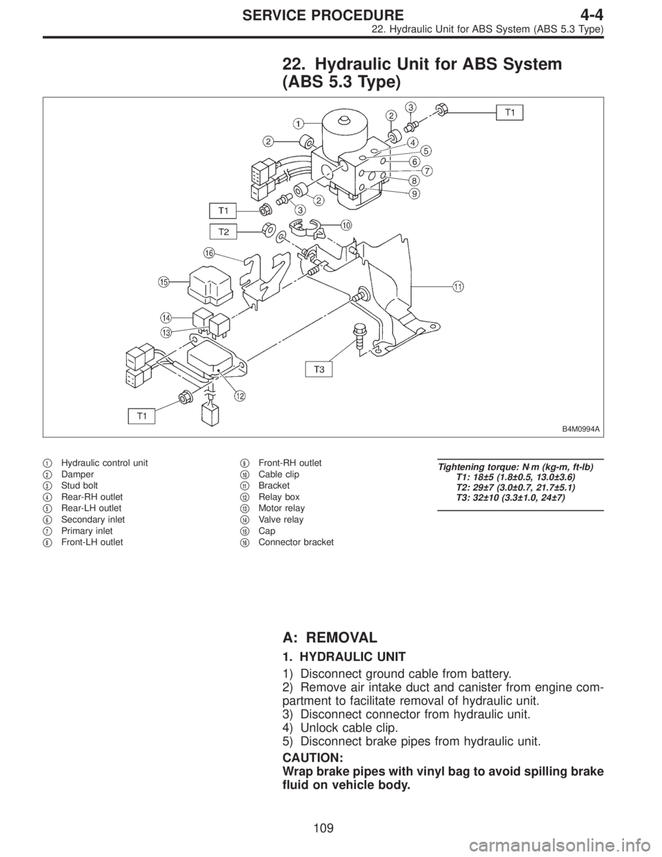
22. Hydraulic Unit for ABS System
(ABS 5.3 Type)
B4M0994A
�1Hydraulic control unit
�
2Damper
�
3Stud bolt
�
4Rear-RH outlet
�
5Rear-LH outlet
�
6Secondary inlet
�
7Primary inlet
�
8Front-LH outlet�
9Front-RH outlet
�
10Cable clip
�
11Bracket
�
12Relay box
�
13Motor relay
�
14Valve relay
�
15Cap
�
16Connector bracket
Tightening torque: N⋅m (kg-m, ft-lb)
T1: 18±5 (1.8±0.5, 13.0±3.6)
T2: 29±7 (3.0±0.7, 21.7±5.1)
T3: 32±10 (3.3±1.0, 24±7)
A: REMOVAL
1. HYDRAULIC UNIT
1) Disconnect ground cable from battery.
2) Remove air intake duct and canister from engine com-
partment to facilitate removal of hydraulic unit.
3) Disconnect connector from hydraulic unit.
4) Unlock cable clip.
5) Disconnect brake pipes from hydraulic unit.
CAUTION:
Wrap brake pipes with vinyl bag to avoid spilling brake
fluid on vehicle body.
109
4-4SERVICE PROCEDURE
22. Hydraulic Unit for ABS System (ABS 5.3 Type)
Page 1321 of 2890
 Check connected and fixed condition of connector.
2) Check valve relay and motor relay for discontinuity or
short circuits.
Condition Terminal number Standard Diagram Terminal locatio")
B: INSPECTION
1) Check connected and fixed condition of connector.
2) Check valve relay and motor relay for discontinuity or
short circuits.
Condition Terminal number Standard Diagram Terminal location
Valve relayTurning off
electricity.85—86 103±10Ω
G4M0456G4M0457
30—87a less than 0.5Ω
30—87 more than 1 MΩ
Turning on
electricity between
85 and 86.
(DC 12 V)30—87a more than 1 MΩ
30—87 less than 0.5Ω
Motor relayTurning off
electricity.85—86 80±8Ω
G4M0458G4M0459
30—87 more than 1 MΩ
Turning on
electricity between
85 and 86.
(DC 12 V)30—87 less than 0.5Ω
C: CHECKING THE HYDRAULIC UNIT ABS
OPERATION
1. CHECKING THE HYDRAULIC UNIT ABS
OPERATION BY PRESSURE GAUGE
1) Lift-up vehicle and remove wheels.
2) Disconnect the air bleeder screws from the FL and FR
caliper bodies.
B4M0633A
3) Connect two pressure gauges to the FL and FR caliper
bodies.
CAUTION:
�Pressure gauges used exclusively for brake fluid
must be used.
�Do not employ pressure gauge previously used for
transmission since the piston seal is expanded which
may lead to malfunction of the brake.
NOTE:
Wrap sealing tape around the pressure gauge.
111
4-4SERVICE PROCEDURE
22. Hydraulic Unit for ABS System (ABS 5.3 Type)
Page 1322 of 2890
![SUBARU LEGACY 1996 Service Repair Manual 4) Bleed air from the pressure gauges.
5) Perform ABS sequence control.
<Ref. to 4-4 [W22D0].>
6) When the hydraulic unit begins to work, and first the FL
side performs decompression, holding, and com](/manual-img/17/57433/w960_57433-1321.png "SUBARU LEGACY 1996 Service Repair Manual 4) Bleed air from the pressure gauges.
5) Perform ABS sequence control.
<Ref. to 4-4 [W22D0].>
6) When the hydraulic unit begins to work, and first the FL
side performs decompression, holding, and com")
4) Bleed air from the pressure gauges.
5) Perform ABS sequence control.
6) When the hydraulic unit begins to work, and first the FL
side performs decompression, holding, and compression,
and then the FR side performs decompression, holding,
and compression.
7) Read values indicated on the pressure gauge and
check if the fluctuation of the values between decompres-
sion and compression meets the standard values. Also
check if any irregular brake pedal tightness is felt.
Initial value When decompressed When compressed
Front wheel 3,432 kPa (35 kg/cm
2, 498 psi)490 kPa (5 kg/cm2, 71 psi)
or less3,432 kPa (35 kg/cm2, 498 psi)
or more
Rear wheel 3,432 kPa (35 kg/cm
2, 498 psi)490 kPa (5 kg/cm2, 71 psi)
or less3,432 kPa (35 kg/cm2, 498 psi)
or more
8) Remove pressure gauges from FL and FR caliper bod-
ies.
9) Remove air bleeder screws from the RL and RR caliper
bodies.
10) Connect the air bleeder screws to the FL and FR cali-
per bodies.
11) Connect two pressure gauges to the RL and RR cali-
per bodies.
12) Bleed air from the pressure gauges and the FL and FR
caliper bodies.
13) Perform ABS sequence control.
14) When the hydraulic unit begins to work, at first the RR
side performs decompression, holding, and compression,
and then the RL side performs decompression, holding,
and compression.
15) Read values indicated on the pressure gauges and
check if they meet the standard value.
16) After checking, remove the pressure gauges from cali-
per bodies.
17) Connect the air bleeder screws to RL and RR caliper
bodies.
18) Bleed air from brake line.
11 2
4-4SERVICE PROCEDURE
22. Hydraulic Unit for ABS System (ABS 5.3 Type)
Page 1323 of 2890
 In the case of AWD AT vehicles, install a spare fuse with
the FWD connector in the engine compartment to simulate
FWD vehicles")
G4M0462
2. CHECKING THE HYDRAULIC UNIT ABS
OPERATION WITH BRAKE TESTER
1) In the case of AWD AT vehicles, install a spare fuse with
the FWD connector in the engine compartment to simulate
FWD vehicles.
2) Prepare for operating ABS sequence control.
4-4 [W22D1] or 4-4 [W22D2].>
G4M0464
3) Set the front wheels or rear wheels on the brake tester
and set the select lever’s position at“neutral”.
4) Operate the brake tester.
5) Perform ABS sequence control.
step 1 or 4-4 [W22D2] step 1.>
6) Hydraulic unit begins to work; and check the following
working sequence.
(1) The FL wheel performs decompression, holding,
and compression in sequence, and subsequently the
FR wheel repeats the cycle.
(2) The RR wheel performs decompression, holding,
and compression in sequence, and subsequently the
RL wheel repeats the cycle.
7) Read values indicated on the brake tester and check if
the fluctuation of values, when decompressed and
compressed, meet the standard values.
Unit: N (kg, lb)
Initial value When decompressed When compressed
Front wheel 981 (100, 221) 490 (50, 110) or less 981 (100, 221) or more
Rear wheel 981 (100, 221) 490 (50, 110) or less 981 (100, 221) or more
8) After checking, also check if any irregular brake pedal
tightness is felt.
11 3
4-4SERVICE PROCEDURE
22. Hydraulic Unit for ABS System (ABS 5.3 Type)
Page 1324 of 2890
 Under the ABS sequence control, after the hydraulic
unit solenoid valve is driven, the operation of the hydraulic
unit can be checked by means of the brake tester or pres-
s")
D: ABS SEQUENCE CONTROL
1) Under the ABS sequence control, after the hydraulic
unit solenoid valve is driven, the operation of the hydraulic
unit can be checked by means of the brake tester or pres-
sure gauge.
2) ABS sequence control can be started by diagnosis con-
nector or select monitor.
B4M0082D
1. OPERATIONAL GUIDELINES OF THE ABS
SEQUENCE CONTROL WITH DIAGNOSIS
CONNECTOR
1) Connect diagnosis terminals to terminals No. 3 and No.
6 of the diagnosis connector beside driver’s seat heater
unit.
2) Set the speed of all wheels at 4 km/h (2 MPH) or less.
3) Turn ignition switch OFF.
4) Within 0.5 seconds after the ABS warning light goes
out, depress the brake pedal and hold it immediately after
ignition switch is turned to ON.
CAUTION:
Do not depress the clutch pedal.
NOTE:
�When the ignition switch is set to on, the brake pedal
must not be depressed.
�Engine must not operate.
5) After completion of ABS sequence control, turn ignition
switch OFF.
2. OPERATIONAL GUIDELINES OF THE ABS
SEQUENCE CONTROL WITH SELECT MONITOR
1) Connect select monitor to data link connector beside
driver’s seat heater unit.
2) Turn ignition switch ON.
3) Put select monitor to ABS mode.
B4M0635
4) PressFD1ENTkey.
11 4
4-4SERVICE PROCEDURE
22. Hydraulic Unit for ABS System (ABS 5.3 Type)
Page 1325 of 2890
B4M0997
5) The message shown in the figure is displayed.
B4M0998
6) The message shown in the figure is displayed as fol-
lows:
(1) When using the brake tester, depress brake pedal
with braking force of 981 N (100 kg, 221 lb).
(2) When using the pressure gauge, depress brake
pedal so as to make the pressure gauge indicate 3,432
kPa (35 kg/cm
2, 498 psi).
CAUTION:
Do not depress the clutch pedal.
B4M0999
7) When the message shown in the figure is displayed,
press ENT key.
8) Check points will be displayed on select monitor.
B4M1000
9) When ABS sequence control cannot be started (by sys-
tem malfunction, etc.), the message shown in the figure will
be displayed.
NOTE:
Read the trouble codes. Repair faulty parts.
B4M1030
10) After completion of ABS sequence control, turn ignition
switch OFF.
11 5
4-4SERVICE PROCEDURE
22. Hydraulic Unit for ABS System (ABS 5.3 Type)
 Install hydraulic unit and bracket.
Tightening torque:
32±7 N⋅m (3.3±0.7 kg-m, 23.9±5.1 ft-lb)
2) Connect brake pipes to their correct hydraulic unit con-
nections. <Re")
 Install hydraulic unit and bracket.
Tightening torque:
32±7 N⋅m (3.3±0.7 kg-m, 23.9±5.1 ft-lb)
2) Connect brake pipes to their correct hydraulic unit con-
nections. <Re")
 The message shown in the figure is displayed.
B4M0998
6) The message shown in the figure is displayed as fol-
lows:
(1) When using the brake tester, depress brake pedal
with braking force o")