Page 1271 of 2890

12. Brake Fluid Replacement
NOTE:
To always maintain the brake fluid characteristics, replace
the brake fluid according to maintenance schedule or ear-
lier than that when used in severe condition.
A: REPLACEMENT
CAUTION:
�The FMVSS No. 116, fresh DOT3 or 4 brake fluid
must be used.
�Cover bleeder with waste cloth, when loosening it,
to prevent brake fluid from being splashed over sur-
rounding parts.
�Avoid mixing different brands of brake fluid to pre-
vent degrading the quality of the fluid.
�Be careful not to allow dirt or dust to get into the
reservoir tank.
NOTE:
�During bleeding operation, keep the brake reserve tank
filled with brake fluid to eliminate entry of air.
�Brake pedal operating must be very slow.
�For convenience and safety, it is advisable to have two
man working.
�The amount of brake fluid required is approximately 500
m�(16.9 US fl oz, 17.6 Imp fl oz) for total brake system.
1) Either jack-up vehicle and place a safety stand under it,
or lift-up vehicle.
2) Remove both front and rear wheels.
3) Draw out the brake fluid from reserve tank with syringe.
4) Refill reservoir tank with recommended brake fluid.
Recommended brake fluid:
FMVSS No. 116, fresh DOT3 or 4 brake fluid
64
4-4SERVICE PROCEDURE
12. Brake Fluid Replacement
Page 1272 of 2890
 Install one end of a vinyl tube onto the air bleeder of and
insert the other end of the tube into a container to collect
the brake fluid.
6) Instruct your co-worker to depre")
G4M0434
G4M0438
G4M0435
5) Install one end of a vinyl tube onto the air bleeder of and
insert the other end of the tube into a container to collect
the brake fluid.
6) Instruct your co-worker to depress the brake pedal
slowly two or three times and then hold it depressed.
7) Loosen bleeder screw approximately 1/4 turn until a
small amount of brake fluid drains into container, and then
quickly tighten screw.
8) Repeat steps 6) and 7) above until there are no air
bubbles in drained brake fluid and new fluid flows through
vinyl tube.
CAUTION:
Add brake fluid as necessary while performing the air
bleed operation, in order to prevent the tank from run-
ning short of brake fluid.
9) After completing the bleeding operation, hold brake
pedal depressed and tighten screw and install bleeder cap.
Tightening torque (Bleeder screw):
8±1 N⋅m (0.8±0.1 kg-m, 5.8±0.7 ft-lb)
10) Bleed air from each wheel cylinder using the same
procedures as described in steps 6) through 7) above.
11) Depress brake pedal with a force of approximately 294
N (30 kg, 66 lb) and hold it there for approximately 20 sec-
onds. At this time check pedal to see if it shows any
unusual movement.
Visually inspect bleeder screws and brake pipe joints to
make sure that there is no fluid leakage.
12) Install wheels, and drive vehicle for a short distance
between 2 to 3 km (1 to 2 miles) to make sure that brakes
are operating properly.
65
4-4SERVICE PROCEDURE
12. Brake Fluid Replacement
Page 1273 of 2890
 Install the oil pressure gauges to measure the master
cylinder fluid pressure (front wheel brake fluid pressure)
and rear wheel cylinde")
G4M0440
13. Proportioning Valve
G4M0668
G4M0915
A: INSPECTION
1) Install the oil pressure gauges to measure the master
cylinder fluid pressure (front wheel brake fluid pressure)
and rear wheel cylinder fluid pressure.
2) Bleed air from the oil pressure gauges.
3) Check the master cylinder fluid pressure and rear wheel
cylinder fluid pressure.
The standard values are shown in Figure.
4) For the oil pressure in case of split point, refer to A:
SPECIFICATIONS 4-4 [S0A0].
B: REMOVAL
1) Remove brake pipe from proportioning valve at four
places.
2) Remove proportioning valve from its bracket.
CAUTION:
Do not disassemble or adjust the proportioning valve.
(The proportioning valve must be replaced as an
assembly.)
C: INSTALLATION
1) Install proportioning valve to bracket.
2) Connect brake pipes correctly to proportioning valve.
3) Bleed air, then check each joint of brake pipe for oil
leaks.
Tightening torque:
Proportioning valve to brake pipe flare nut:
15
+3
�2N⋅m (1.5+0.3
�0.2kg-m, 10.8+2.2
�1.4ft-lb)
Proportioning valve to bracket:
18±5 N⋅m (1.8±0.5 kg-m, 13.0±3.6 ft-lb)
66
4-4SERVICE PROCEDURE
13. Proportioning Valve
Page 1274 of 2890
14. ABS Sensor
A: REMOVAL
1. FRONT ABS SENSOR
1) Disconnect front ABS sensor connector located in
engine compartment.
B4M0079A
2) Remove bolts which secure sensor harness to strut.
G4M0451
3) Remove bolts which secure sensor harness to body.
G4M0443
4) Remove bolts which secure front ABS sensor to
housing, and remove front ABS sensor.
CAUTION:
�Be careful not to damage pole piece located at tip of
the sensor and teeth faces during removal.
�Do not pull sensor harness during removal.
5) Remove front disc brake caliper and disc rotor from
housing after removing front tire.
6) Remove front drive shaft and housing and hub assem-
bly.
67
4-4SERVICE PROCEDURE
14. ABS Sensor
Page 1280 of 2890

B4M0069A
�1Connector
�
2Cap
�
3Motor relay
�
4Valve relay
�
5Hydraulic control unit
�
6Front-RH outlet
�
7Rear-LH outlet�
8Rear-RH outlet
�
9Fro")
15. Hydraulic Unit for ABS System
(Except ABS 5.3 Type)
B4M0069A
�1Connector
�
2Cap
�
3Motor relay
�
4Valve relay
�
5Hydraulic control unit
�
6Front-RH outlet
�
7Rear-LH outlet�
8Rear-RH outlet
�
9Front-LH outlet
�
10Primary inlet
�
11Secondary inlet
�
12Bracket
Tightening torque: N⋅m (kg-m, ft-lb)
T1: 1.2±0.2
(0.125±0.025, 0.9±0.2)
T2: 18±5 (1.8±0.5, 13.0±3.6)
T3: 29±7 (3.0±0.7, 21.7±5.1)
T4: 32±10 (3.3±1.0, 24±7)
A: REMOVAL
1) Remove air intake duct.
2) Remove canister from engine compartment to facilitate
removal of hydraulic unit.
3) Disconnect brake pipes from hydraulic unit and plug
open joints to prevent entry of foreign particles.
G4M0455
4) Remove nuts and bolts which secure hydraulic unit, and
remove hydraulic unit from engine compartment.
CAUTION:
�Hydraulic unit cannot be disassembled. Do not
attempt to loosen bolts and nuts.
�Do not drop or bump hydraulic unit.
�Do not turn the hydraulic unit upside down or place
it on its side.
73
4-4SERVICE PROCEDURE
15. Hydraulic Unit for ABS System (Except ABS 5.3 Type)
Page 1282 of 2890
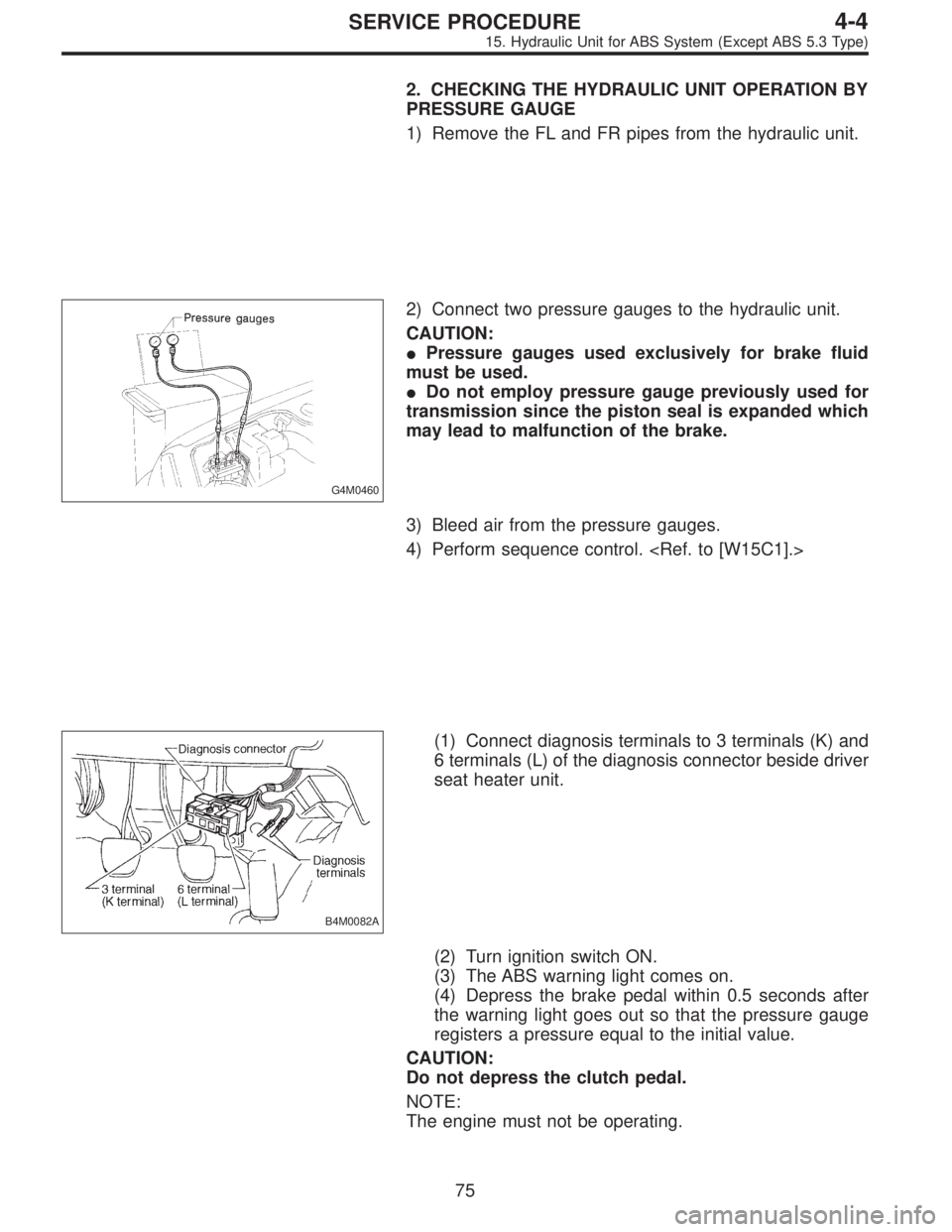
2. CHECKING THE HYDRAULIC UNIT OPERATION BY
PRESSURE GAUGE
1) Remove the FL and FR pipes from the hydraulic unit.
G4M0460
2) Connect two pressure gauges to the hydraulic unit.
CAUTION:
�Pressure gauges used exclusively for brake fluid
must be used.
�Do not employ pressure gauge previously used for
transmission since the piston seal is expanded which
may lead to malfunction of the brake.
3) Bleed air from the pressure gauges.
4) Perform sequence control.
B4M0082A
(1) Connect diagnosis terminals to 3 terminals (K) and
6 terminals (L) of the diagnosis connector beside driver
seat heater unit.
(2) Turn ignition switch ON.
(3) The ABS warning light comes on.
(4) Depress the brake pedal within 0.5 seconds after
the warning light goes out so that the pressure gauge
registers a pressure equal to the initial value.
CAUTION:
Do not depress the clutch pedal.
NOTE:
The engine must not be operating.
75
4-4SERVICE PROCEDURE
15. Hydraulic Unit for ABS System (Except ABS 5.3 Type)
Page 1283 of 2890
 When the hydraulic unit begins to work, and first the FL
side performs decompression, holding, and compression,
and then the FR side performs decompression, holding,
and compression.
6) Read values")
5) When the hydraulic unit begins to work, and first the FL
side performs decompression, holding, and compression,
and then the FR side performs decompression, holding,
and compression.
6) Read values indicated on the pressure gauge and
check if the fluctuation of the values between decompres-
sion and compression meets the standard values. Also
check if any irregular brake pedal tightness is felt.
Initial value When decompressed When compressed
Front wheel 3,432 kPa (35 kg/cm
2, 498 psi) 490 kPa (5 kg/cm2, 71 psi) 3,432 kPa (35 kg/cm2, 498 psi)
Rear wheel 3,432 kPa (35 kg/cm
2, 498 psi) 490 kPa (5 kg/cm2, 71psi) 3,432 kPa (35 kg/cm2, 498 psi)
�In case of hydraulic unit plunger piston malfunction:
Initial value When decompressed When compressed
Rear right wheel 3,432 kPa (35 kg/cm
2, 498 psi) 490 kPa (5 kg/cm2, 71 psi) 3,432 kPa (35 kg/cm2, 498 psi)
Rear left wheel 3,432 kPa (35 kg/cm
2, 498 psi) 3,432 kPa (35 kg/cm2, 498 psi) 3,432 kPa (35 kg/cm2, 498 psi)
7) Remove pressure gauges and RL and RR pipes from
the hydraulic unit.
8) Connect the FL and FR pipes to the hydraulic unit.
9) Connect two pressure gauges to the hydraulic unit.
10) Bleed air from the pressure gauges and the FL and FR
wheel cylinders.
11) Repeat step 4) procedures.
12) The hydraulic unit begins to work, and simultaneously
the RL and RR wheel cylinders perform decompression,
holding, and compression.
13) Read values indicated on the pressure gauges and
check if they meet the standard value.
14) After checking, remove the pressure gauges from the
RL and RR pipes and connect the RL and RR pipes to the
hydraulic unit, and bleed air.
76
4-4SERVICE PROCEDURE
15. Hydraulic Unit for ABS System (Except ABS 5.3 Type)
Page 1284 of 2890
 In the case of AWD vehicles, install a spare fuse with
the FWD connector in the engine compartment to simulate
FWD vehicles.
B4M0082A
2) Con")
G4M0462
3. CHECKING THE HYDRAULIC UNIT WITH BRAKE
TESTER
1) In the case of AWD vehicles, install a spare fuse with
the FWD connector in the engine compartment to simulate
FWD vehicles.
B4M0082A
2) Connect diagnosis terminals to 3 terminals (K) and 6
terminals (L) of the diagnosis connector beside driver seat
heater unit.
G4M0464
3) Set the front wheels or rear wheels on the brake tester
and set the select lever’s position at“neutral”.
4) Operate the brake tester.
5) Perform sequence control.
(1) Turn ignition switch ON.
(2) The ABS warning light comes on.
(3) Depress the brake pedal within 0.5 seconds after
the warning light goes out so that the brake tester reg-
isters a pressure equal to the initial value.
CAUTION:
Do not depress the clutch pedal.
NOTE:
The engine must not be operating.
6) Hydraulic unit begins to work; and check the following
working sequence.
(1) The left front wheel performs decompression,
holding, and compression in sequence, and subse-
quently the right front wheel repeats the cycle.
(2) Simultaneously both right and left rear wheel per-
form decompression, holding, and compression in
sequence.
77
4-4SERVICE PROCEDURE
15. Hydraulic Unit for ABS System (Except ABS 5.3 Type)
 Disconnect front ABS sensor connector located in
engine compartment.
B4M0079A
2) Remove bolts which secure sensor harness to strut.
G4M0451
3) Remove b")