Page 1255 of 2890
D: ASSEMBLY
1. PRECAUTIONS FOR ASSEMBLING
1) When assembling, be sure to use recommended brake
fluid.
2) Ensure that the inside wall of cylinder, pistons, and pis-
ton cups are free from dirt when assembling.
3) Be extremely careful not to damage, scratch, or dent
cylinder inside wall, pistons, and piston cups.
4) Do not drop parts. Never attempt to use any part that
has been dropped accidentally.
2. ASSEMBLING OPERATION
1) Assembling piston assembly:
Apply recommended brake fluid to inside wall of cylinder,
and to outer surface of piston assembly, and install piston
assemblies carefully into cylinder.
2) Assembling supply valve stopper or cylinder pin:
After installing piston into cylinder, push primary piston in
about 10 mm (0.39 in), using a rod, such as push rod then
assemble gasket and supply valve stopper or cylinder pin.
Tightening torque:
2.2±0.7 N⋅m (0.225±0.075 kg-m, 1.6±0.5 ft-lb)
CAUTION:
If the gasket and supply valve stopper are assembled
without pushing in the primary piston, scratches may
be caused on the secondary piston, and no pressure
may be built up in the secondary side. To avoid such
an error, be sure to push in the primary piston before
assembling these parts.
3) Assembling C-ring:
With primary piston pushed in slightly, attach C-ring by
using C-ring pliers.
NOTE:
After assembling, ensure that the C-ring is fitted securely
in the ring groove.
E: INSTALLATION
To install the master cylinder to the body, reverse the
sequence of removal procedure.
Tightening torque:
Master cylinder mounting nut
14±4 N⋅m (1.4±0.4 kg-m, 10.1±2.9 ft-lb)
Piping flare nut
15
+3
�2N⋅m (1.5+0.3
�0.2kg-m, 10.8+2.2
�1.4ft-lb)
CAUTION:
Be sure to use recommended brake fluid.
49
4-4SERVICE PROCEDURE
5. Master Cylinder
Page 1256 of 2890
6. Brake Booster
A: REMOVAL
1) Remove or disconnect the following parts at engine
compartment.
(1) Disconnect connector for brake fluid level indicator.
(2) Remove brake pipes from master cylinder.
(3) Remove master cylinder installing nuts.
(4) Disconnect vacuum hose from brake booster.
2) Remove the following parts from the pedal bracket.
(1) Snap pin and clevis pin
(2) Four brake booster installing nuts
3) Remove brake booster while shunning brake pipes.
B4M0117A
B: INSTALLATION
1) Mount brake booster in position.
2) Connect operating rod to brake pedal with clevis pin
and snap pin.
�
1Clevis pin
�
2Snap pin
�
3Operating rod
G4M0420
3) Connect vacuum hose to brake booster.
4) Mount master cylinder onto brake booster.
5) Connect brake pipes to master cylinder.
6) Connect electric connector for brake fluid level indica-
tor.
50
4-4SERVICE PROCEDURE
6. Brake Booster
Page 1257 of 2890
B4M0616A
B4M0617A
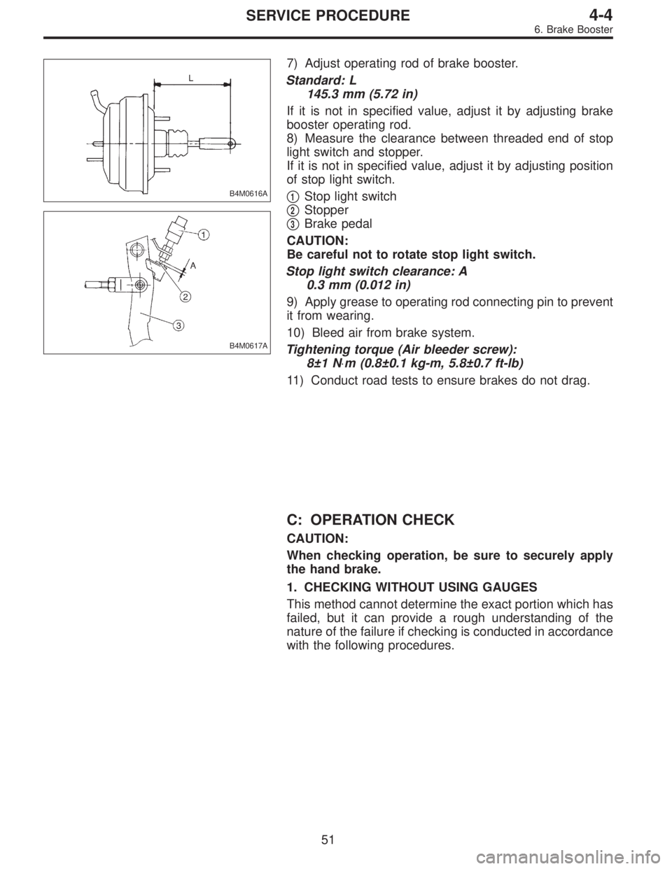
7) Adjust operating rod of brake booster.
Standard: L
145.3 mm (5.72 in)
If it is not in specified value, adjust it by adjusting brake
booster operating rod.
8) Measure the clearance between threaded end of stop
light switch and stopper.
If it is not in specified value, adjust it by adjusting position
of stop light switch.
�
1Stop light switch
�
2Stopper
�
3Brake pedal
CAUTION:
Be careful not to rotate stop light switch.
Stop light switch clearance: A
0.3 mm (0.012 in)
9) Apply grease to operating rod connecting pin to prevent
it from wearing.
10) Bleed air from brake system.
Tightening torque (Air bleeder screw):
8±1 N⋅m (0.8±0.1 kg-m, 5.8±0.7 ft-lb)
11) Conduct road tests to ensure brakes do not drag.
C: OPERATION CHECK
CAUTION:
When checking operation, be sure to securely apply
the hand brake.
1. CHECKING WITHOUT USING GAUGES
This method cannot determine the exact portion which has
failed, but it can provide a rough understanding of the
nature of the failure if checking is conducted in accordance
with the following procedures.
51
4-4SERVICE PROCEDURE
6. Brake Booster
Page 1258 of 2890
G4M0744
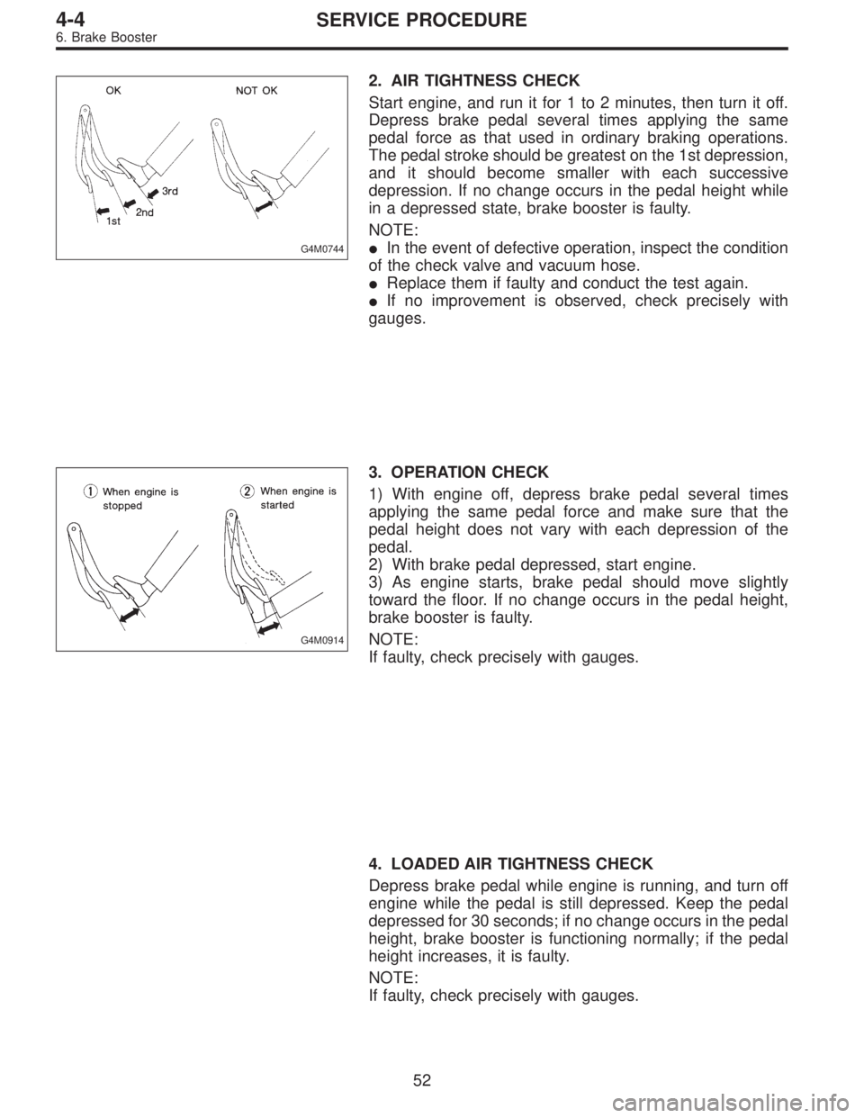
2. AIR TIGHTNESS CHECK
Start engine, and run it for 1 to 2 minutes, then turn it off.
Depress brake pedal several times applying the same
pedal force as that used in ordinary braking operations.
The pedal stroke should be greatest on the 1st depression,
and it should become smaller with each successive
depression. If no change occurs in the pedal height while
in a depressed state, brake booster is faulty.
NOTE:
�In the event of defective operation, inspect the condition
of the check valve and vacuum hose.
�Replace them if faulty and conduct the test again.
�If no improvement is observed, check precisely with
gauges.
G4M0914
3. OPERATION CHECK
1) With engine off, depress brake pedal several times
applying the same pedal force and make sure that the
pedal height does not vary with each depression of the
pedal.
2) With brake pedal depressed, start engine.
3) As engine starts, brake pedal should move slightly
toward the floor. If no change occurs in the pedal height,
brake booster is faulty.
NOTE:
If faulty, check precisely with gauges.
4. LOADED AIR TIGHTNESS CHECK
Depress brake pedal while engine is running, and turn off
engine while the pedal is still depressed. Keep the pedal
depressed for 30 seconds; if no change occurs in the pedal
height, brake booster is functioning normally; if the pedal
height increases, it is faulty.
NOTE:
If faulty, check precisely with gauges.
52
4-4SERVICE PROCEDURE
6. Brake Booster
Page 1259 of 2890
G4M0423
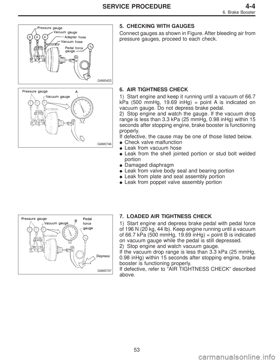
5. CHECKING WITH GAUGES
Connect gauges as shown in Figure. After bleeding air from
pressure gauges, proceed to each check.
G4M0746
6. AIR TIGHTNESS CHECK
1) Start engine and keep it running until a vacuum of 66.7
kPa (500 mmHg, 19.69 inHg) = point A is indicated on
vacuum gauge. Do not depress brake pedal.
2) Stop engine and watch the gauge. If the vacuum drop
range is less than 3.3 kPa (25 mmHg, 0.98 inHg) within 15
seconds after stopping engine, brake booster is functioning
properly.
If defective, the cause may be one of those listed below.
�Check valve malfunction
�Leak from vacuum hose
�Leak from the shell jointed portion or stud bolt welded
portion
�Damaged diaphragm
�Leak from valve body seal and bearing portion
�Leak from plate and seal assembly portion
�Leak from poppet valve assembly portion
G4M0747
7. LOADED AIR TIGHTNESS CHECK
1) Start engine and depress brake pedal with pedal force
of 196 N (20 kg, 44 lb). Keep engine running until a vacuum
of 66.7 kPa (500 mmHg, 19.69 inHg) = point B is indicated
on vacuum gauge while the pedal is still depressed.
2) Stop engine and watch vacuum gauge.
If the vacuum drop range is less than 3.3 kPa (25 mmHg,
0.98 inHg) within 15 seconds after stopping engine, brake
booster is functioning properly.
If defective, refer to“AIR TIGHTNESS CHECK”described
above.
53
4-4SERVICE PROCEDURE
6. Brake Booster
Page 1260 of 2890
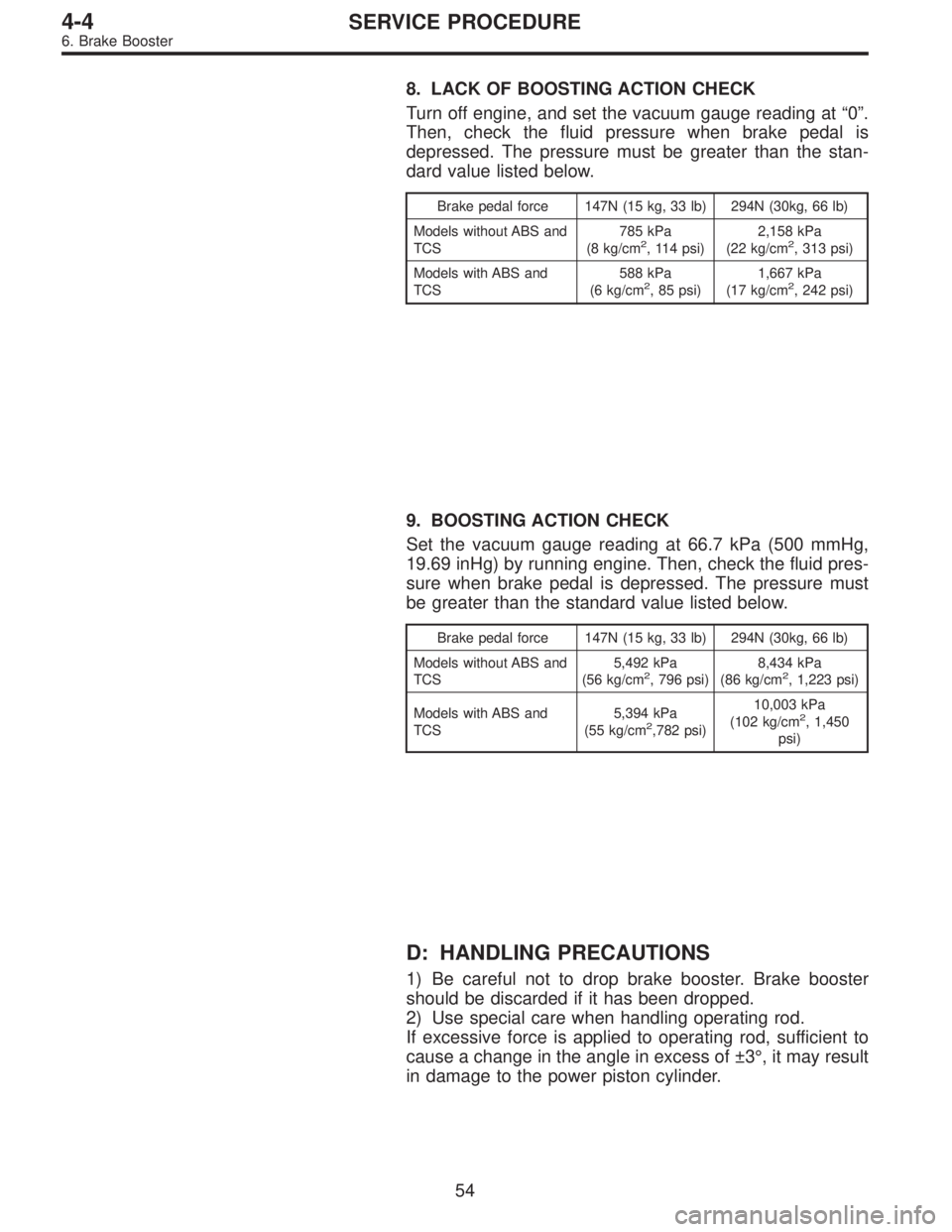
8. LACK OF BOOSTING ACTION CHECK
Turn off engine, and set the vacuum gauge reading at“0”.
Then, check the fluid pressure when brake pedal is
depressed. The pressure must be greater than the stan-
dard value listed below.
Brake pedal force 147N (15 kg, 33 lb) 294N (30kg, 66 lb)
Models without ABS and
TCS785 kPa
(8 kg/cm
2, 114 psi)2,158 kPa
(22 kg/cm2, 313 psi)
Models with ABS and
TCS588 kPa
(6 kg/cm
2, 85 psi)1,667 kPa
(17 kg/cm2, 242 psi)
9. BOOSTING ACTION CHECK
Set the vacuum gauge reading at 66.7 kPa (500 mmHg,
19.69 inHg) by running engine. Then, check the fluid pres-
sure when brake pedal is depressed. The pressure must
be greater than the standard value listed below.
Brake pedal force 147N (15 kg, 33 lb) 294N (30kg, 66 lb)
Models without ABS and
TCS5,492 kPa
(56 kg/cm
2, 796 psi)8,434 kPa
(86 kg/cm2, 1,223 psi)
Models with ABS and
TCS5,394 kPa
(55 kg/cm
2,782 psi)10,003 kPa
(102 kg/cm2, 1,450
psi)
D: HANDLING PRECAUTIONS
1) Be careful not to drop brake booster. Brake booster
should be discarded if it has been dropped.
2) Use special care when handling operating rod.
If excessive force is applied to operating rod, sufficient to
cause a change in the angle in excess of ±3°, it may result
in damage to the power piston cylinder.
54
4-4SERVICE PROCEDURE
6. Brake Booster
Page 1261 of 2890
G4M0425
3) Use care when placing brake booster on the floor.
CAUTION:
If external force is applied from above when brake
booster is placed in this position, the resin portion as
indicated by“P”, may be damaged.
G4M0424
4) Do not change the push rod length. If it has been
changed, reset the projected length“L”to the standard
length.
Standard:
L = 10 mm (0.39 in)
55
4-4SERVICE PROCEDURE
6. Brake Booster
Page 1262 of 2890
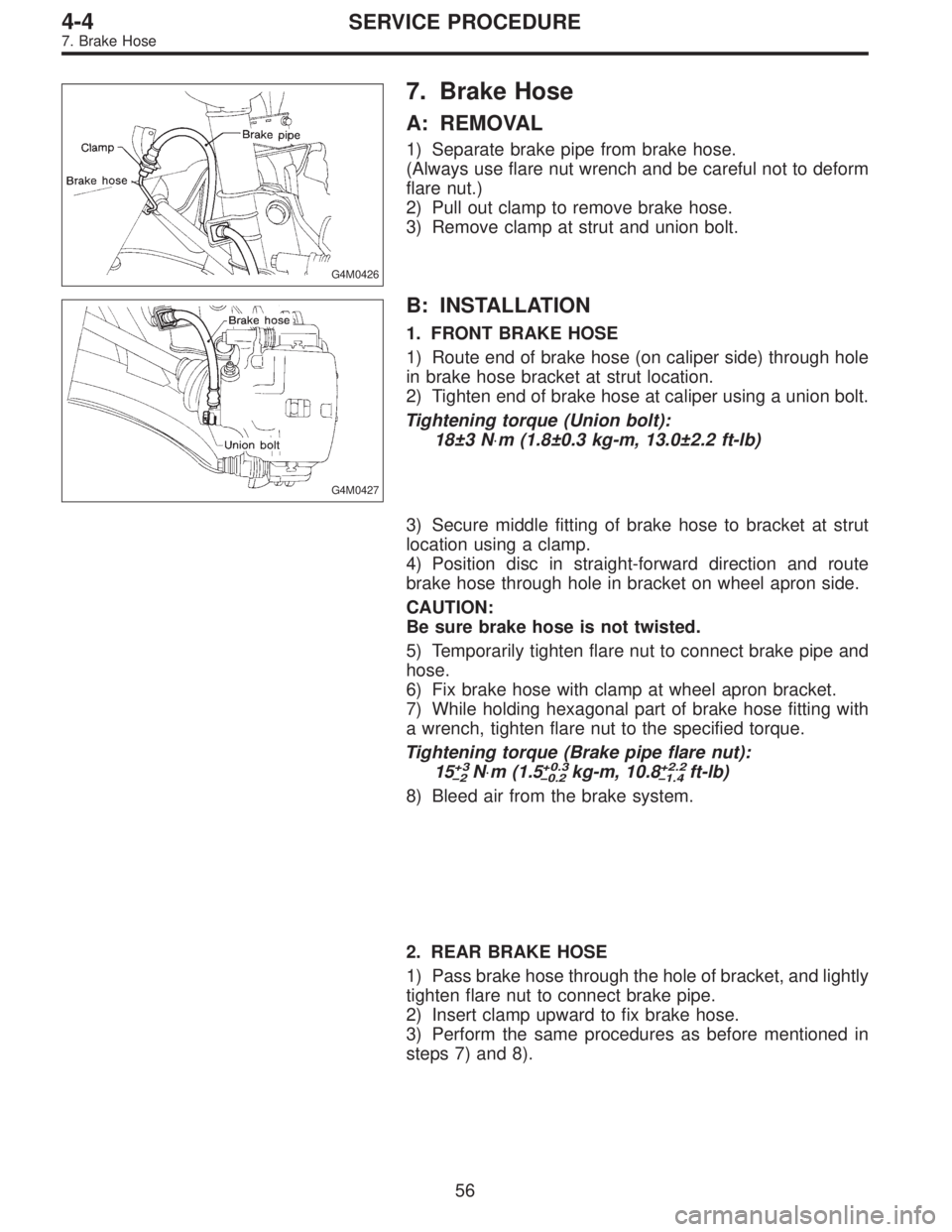
G4M0426
7. Brake Hose
A: REMOVAL
1) Separate brake pipe from brake hose.
(Always use flare nut wrench and be careful not to deform
flare nut.)
2) Pull out clamp to remove brake hose.
3) Remove clamp at strut and union bolt.
G4M0427
B: INSTALLATION
1. FRONT BRAKE HOSE
1) Route end of brake hose (on caliper side) through hole
in brake hose bracket at strut location.
2) Tighten end of brake hose at caliper using a union bolt.
Tightening torque (Union bolt):
18±3 N⋅m (1.8±0.3 kg-m, 13.0±2.2 ft-lb)
3) Secure middle fitting of brake hose to bracket at strut
location using a clamp.
4) Position disc in straight-forward direction and route
brake hose through hole in bracket on wheel apron side.
CAUTION:
Be sure brake hose is not twisted.
5) Temporarily tighten flare nut to connect brake pipe and
hose.
6) Fix brake hose with clamp at wheel apron bracket.
7) While holding hexagonal part of brake hose fitting with
a wrench, tighten flare nut to the specified torque.
Tightening torque (Brake pipe flare nut):
15
+3
�2N⋅m (1.5+0.3
�0.2kg-m, 10.8+2.2
�1.4ft-lb)
8) Bleed air from the brake system.
2. REAR BRAKE HOSE
1) Pass brake hose through the hole of bracket, and lightly
tighten flare nut to connect brake pipe.
2) Insert clamp upward to fix brake hose.
3) Perform the same procedures as before mentioned in
steps 7) and 8).
56
4-4SERVICE PROCEDURE
7. Brake Hose