Page 1214 of 2890
1. Front Disc Brake
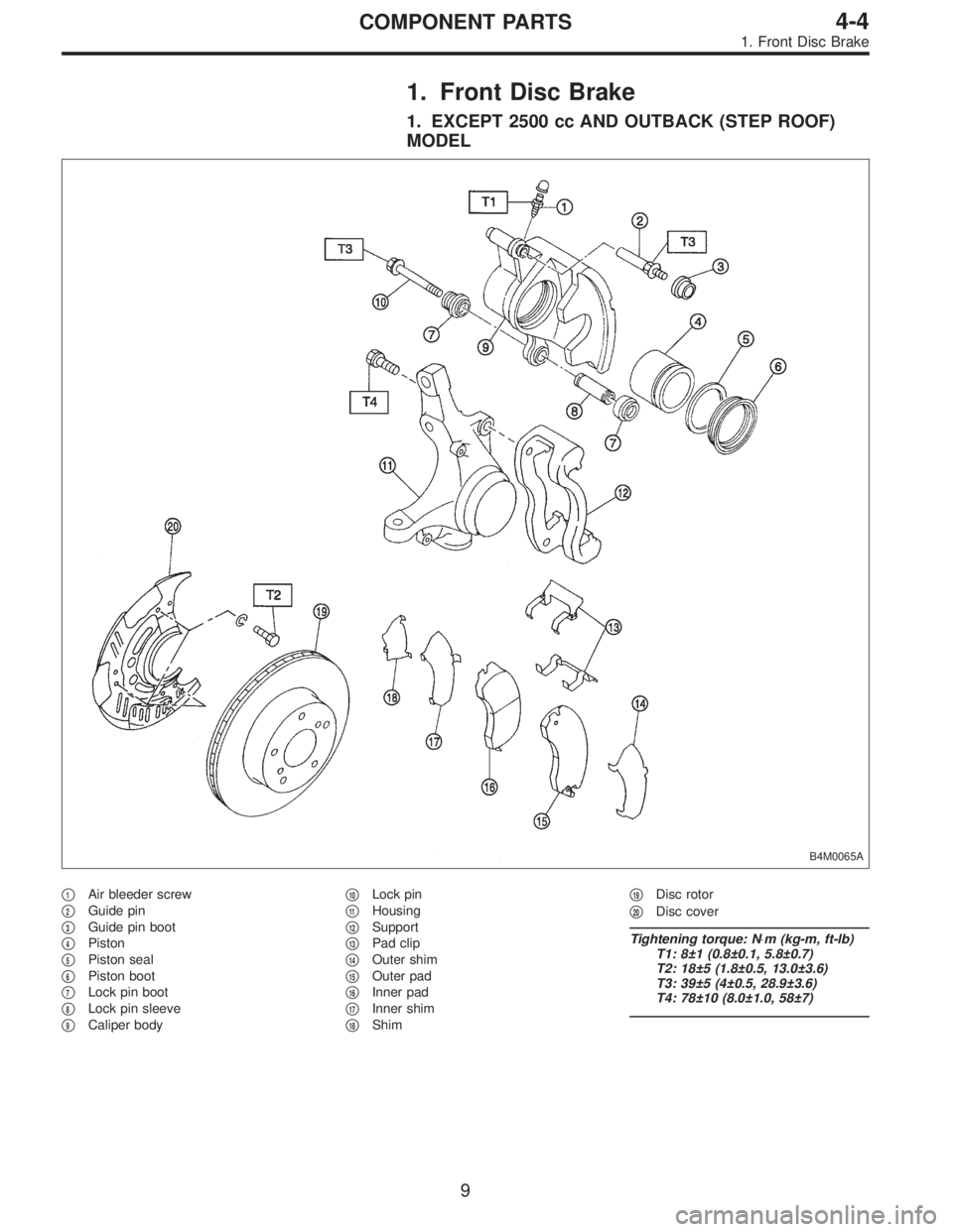
1. EXCEPT 2500 cc AND OUTBACK (STEP ROOF)
MODEL
B4M0065A
�1Air bleeder screw
�
2Guide pin
�
3Guide pin boot
�
4Piston
�
5Piston seal
�
6Piston boot
�
7Lock pin boot
�
8Lock pin sleeve
�
9Caliper body�
10Lock pin
�
11Housing
�
12Support
�
13Pad clip
�
14Outer shim
�
15Outer pad
�
16Inner pad
�
17Inner shim
�
18Shim�
19Disc rotor
�
20Disc cover
Tightening torque: N⋅m (kg-m, ft-lb)
T1: 8±1 (0.8±0.1, 5.8±0.7)
T2: 18±5 (1.8±0.5, 13.0±3.6)
T3: 39±5 (4±0.5, 28.9±3.6)
T4: 78±10 (8.0±1.0, 58±7)
9
4-4COMPONENT PARTS
1. Front Disc Brake
Page 1215 of 2890
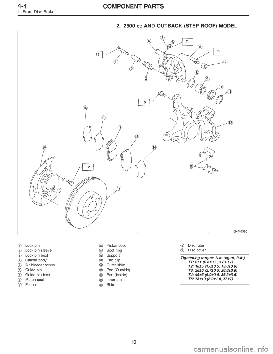
2. 2500 cc AND OUTBACK (STEP ROOF) MODEL
G4M0990
�1Lock pin
�
2Lock pin sleeve
�
3Lock pin boot
�
4Caliper body
�
5Air bleeder screw
�
6Guide pin
�
7Guide pin boot
�
8Piston seal
�
9Piston�
10Piston boot
�
11Boot ring
�
12Support
�
13Pad clip
�
14Outer shim
�
15Pad (Outside)
�
16Pad (Inside)
�
17Inner shim
�
18Shim�
19Disc rotor
�
20Disc cover
Tightening torque: N⋅m (kg-m, ft-lb)
T1: 8±1 (0.8±0.1, 5.8±0.7)
T2: 18±5 (1.8±0.5, 13.0±3.6)
T3: 36±5 (3.7±0.5, 26.8±3.6)
T4: 49±5 (5.0±0.5, 36.2±3.6)
T5: 78±10 (8.0±1.0, 58±7)
10
4-4COMPONENT PARTS
1. Front Disc Brake
Page 1216 of 2890
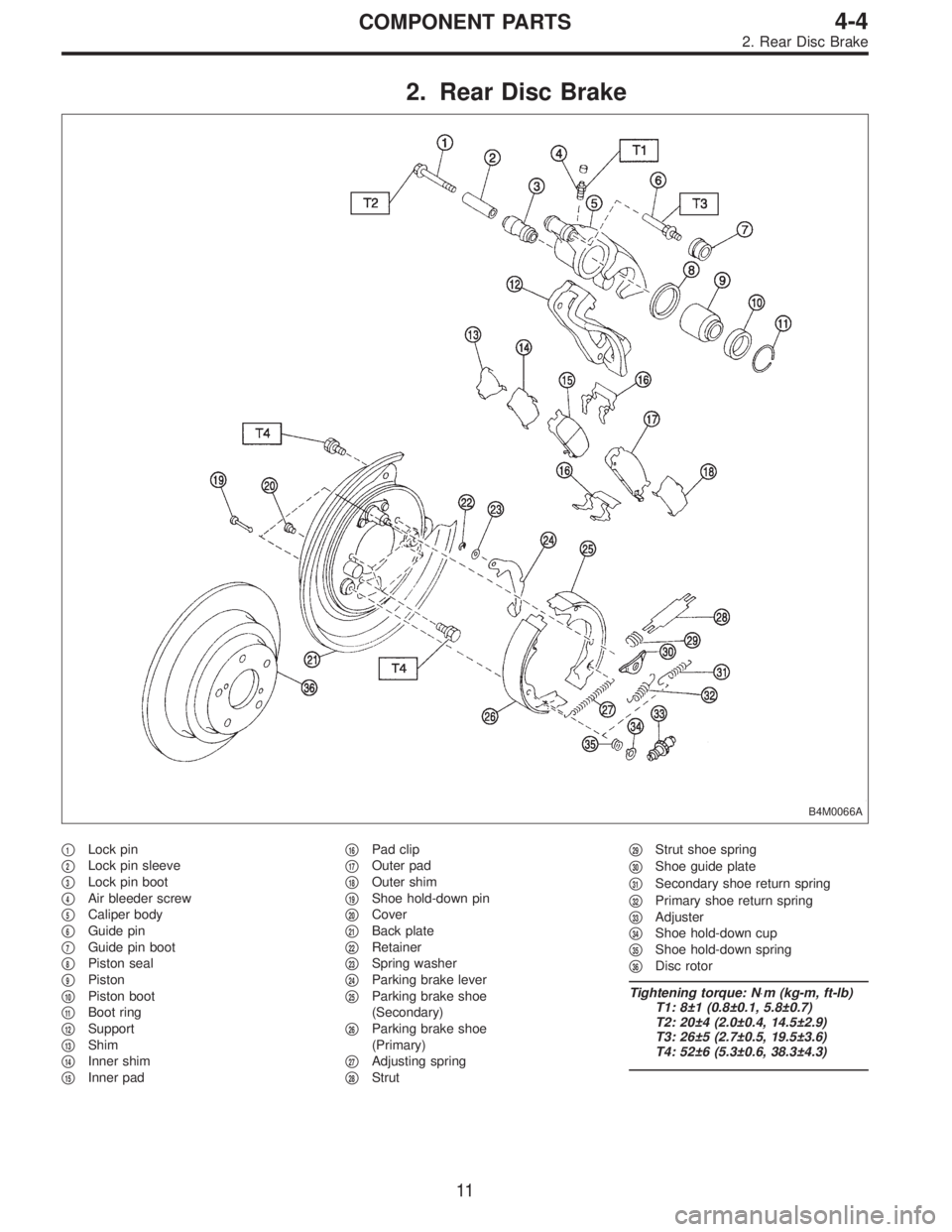
2. Rear Disc Brake
B4M0066A
�1Lock pin
�
2Lock pin sleeve
�
3Lock pin boot
�
4Air bleeder screw
�
5Caliper body
�
6Guide pin
�
7Guide pin boot
�
8Piston seal
�
9Piston
�
10Piston boot
�
11Boot ring
�
12Support
�
13Shim
�
14Inner shim
�
15Inner pad�
16Pad clip
�
17Outer pad
�
18Outer shim
�
19Shoe hold-down pin
�
20Cover
�
21Back plate
�
22Retainer
�
23Spring washer
�
24Parking brake lever
�
25Parking brake shoe
(Secondary)
�
26Parking brake shoe
(Primary)
�
27Adjusting spring
�
28Strut�
29Strut shoe spring
�
30Shoe guide plate
�
31Secondary shoe return spring
�
32Primary shoe return spring
�
33Adjuster
�
34Shoe hold-down cup
�
35Shoe hold-down spring
�
36Disc rotor
Tightening torque: N⋅m (kg-m, ft-lb)
T1: 8±1 (0.8±0.1, 5.8±0.7)
T2: 20±4 (2.0±0.4, 14.5±2.9)
T3: 26±5 (2.7±0.5, 19.5±3.6)
T4: 52±6 (5.3±0.6, 38.3±4.3)
11
4-4COMPONENT PARTS
2. Rear Disc Brake
Page 1217 of 2890
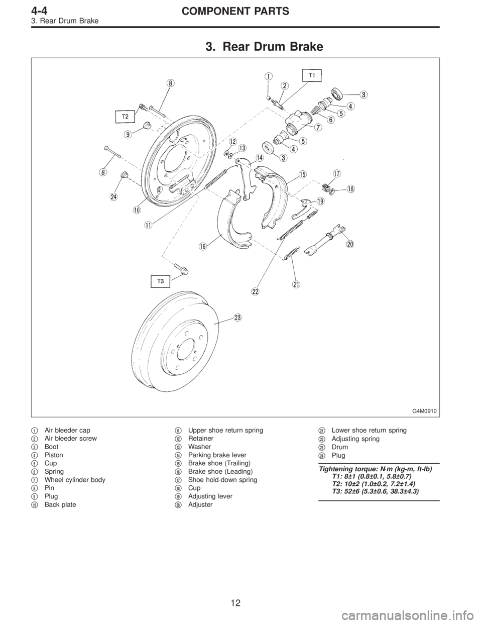
3. Rear Drum Brake
G4M0910
�1Air bleeder cap
�
2Air bleeder screw
�
3Boot
�
4Piston
�
5Cup
�
6Spring
�
7Wheel cylinder body
�
8Pin
�
9Plug
�
10Back plate�
11Upper shoe return spring
�
12Retainer
�
13Washer
�
14Parking brake lever
�
15Brake shoe (Trailing)
�
16Brake shoe (Leading)
�
17Shoe hold-down spring
�
18Cup
�
19Adjusting lever
�
20Adjuster�
21Lower shoe return spring
�
22Adjusting spring
�
23Drum
�
24Plug
Tightening torque: N⋅m (kg-m, ft-lb)
T1: 8±1 (0.8±0.1, 5.8±0.7)
T2: 10±2 (1.0±0.2, 7.2±1.4)
T3: 52±6 (5.3±0.6, 38.3±4.3)
12
4-4COMPONENT PARTS
3. Rear Drum Brake
Page 1220 of 2890
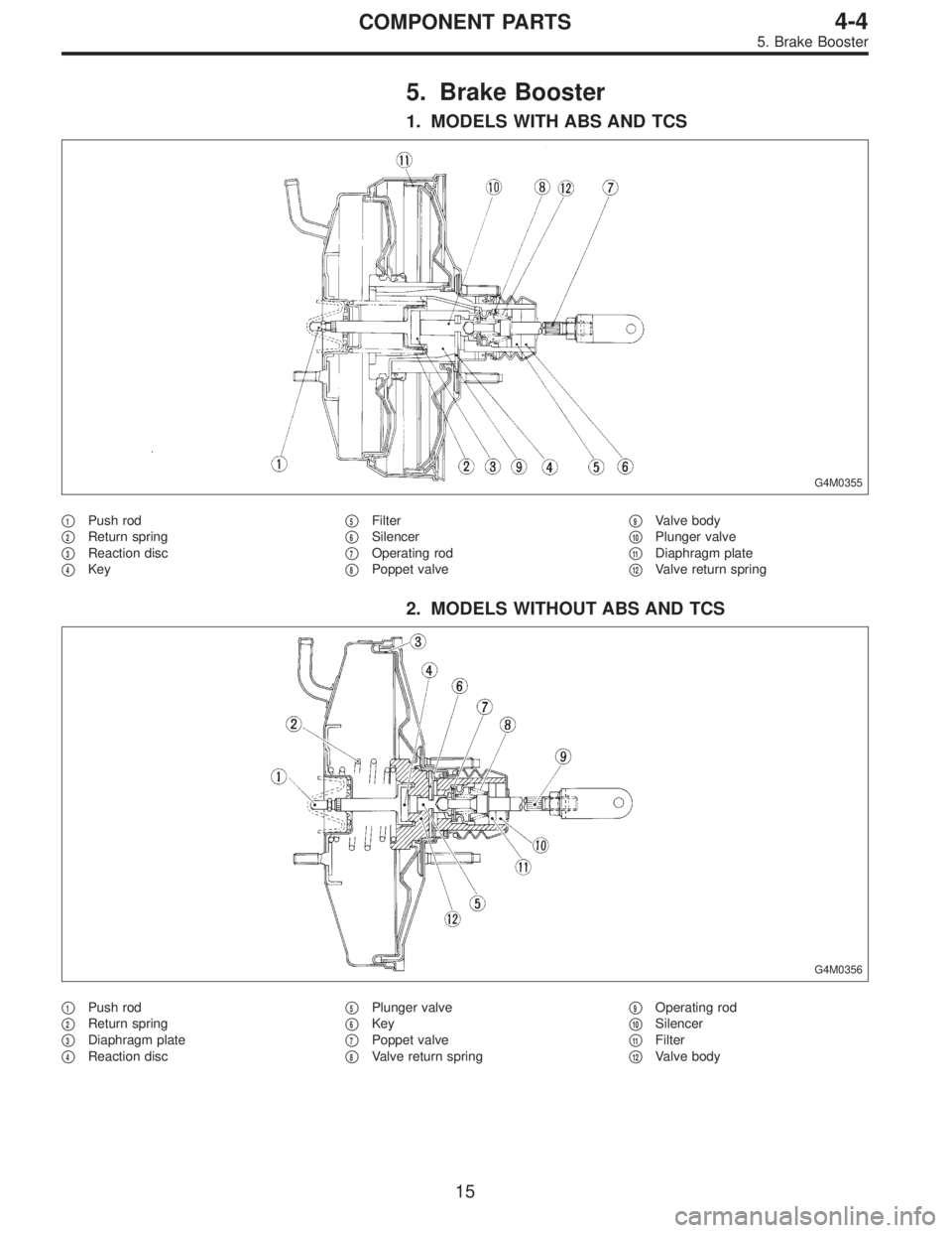
5. Brake Booster
1. MODELS WITH ABS AND TCS
G4M0355
�1Push rod
�
2Return spring
�
3Reaction disc
�
4Key�
5Filter
�
6Silencer
�
7Operating rod
�
8Poppet valve�
9Valve body
�
10Plunger valve
�
11Diaphragm plate
�
12Valve return spring
2. MODELS WITHOUT ABS AND TCS
G4M0356
�1Push rod
�
2Return spring
�
3Diaphragm plate
�
4Reaction disc�
5Plunger valve
�
6Key
�
7Poppet valve
�
8Valve return spring�
9Operating rod
�
10Silencer
�
11Filter
�
12Valve body
15
4-4COMPONENT PARTS
5. Brake Booster
Page 1226 of 2890
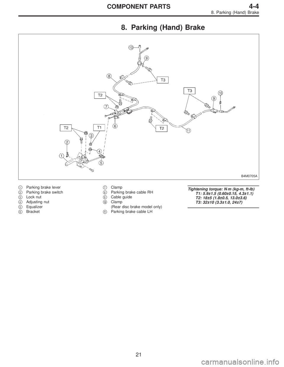
8. Parking (Hand) Brake
B4M0705A
�1Parking brake lever
�
2Parking brake switch
�
3Lock nut
�
4Adjusting nut
�
5Equalizer
�
6Bracket�
7Clamp
�
8Parking brake cable RH
�
9Cable guide
�
10Clamp
(Rear disc brake model only)
�
11Parking brake cable LH
Tightening torque: N⋅m (kg-m, ft-lb)
T1: 5.9±1.5 (0.60±0.15, 4.3±1.1)
T2: 18±5 (1.8±0.5, 13.0±3.6)
T3: 32±10 (3.3±1.0, 24±7)
21
4-4COMPONENT PARTS
8. Parking (Hand) Brake
Page 1229 of 2890
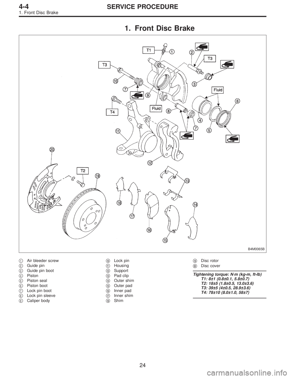
1. Front Disc Brake
B4M0065B
�1Air bleeder screw
�
2Guide pin
�
3Guide pin boot
�
4Piston
�
5Piston seal
�
6Piston boot
�
7Lock pin boot
�
8Lock pin sleeve
�
9Caliper body�
10Lock pin
�
11Housing
�
12Support
�
13Pad clip
�
14Outer shim
�
15Outer pad
�
16Inner pad
�
17Inner shim
�
18Shim�
19Disc rotor
�
20Disc cover
Tightening torque: N⋅m (kg-m, ft-lb)
T1: 8±1 (0.8±0.1, 5.8±0.7)
T2: 18±5 (1.8±0.5, 13.0±3.6)
T3: 39±5 (4±0.5, 28.9±3.6)
T4: 78±10 (8.0±1.0, 58±7)
24
4-4SERVICE PROCEDURE
1. Front Disc Brake
Page 1230 of 2890
 Remove lock pin.
2) Raise caliper body.
3) Remove pad.
G4M0362
4) Check pad thickness A.
Pad thickness
(including back metal)
mm (in)Standard value 17 (0.67)
Wear l")
G4M0361
A: ON-CAR SERVICE
1. PAD
1) Remove lock pin.
2) Raise caliper body.
3) Remove pad.
G4M0362
4) Check pad thickness A.
Pad thickness
(including back metal)
mm (in)Standard value 17 (0.67)
Wear limit 7.5 (0.295)
CAUTION:
�Always replace the pads for both the left and right
wheels at the same time. Also replace pad clips if they
are twisted or worn.
�A wear indicator is provided on the inner disc brake
pad. If the pad wears down to such an extent that the
end of the wear indicator contacts the disc rotor, a
squeaking sound is produced as the wheel rotates. If
this sound is heard, replace the pad.
�Replace pad if there is oil or grease on it.
G4M0363
5) Apply thin coat of PBC GREASE (Part No. 003607000)
to the frictional portion between pad and pad clip.
6) Install pads on support.
7) Install caliper body on support.
NOTE:
If it is difficult to push piston during pad replacement,
loosen air bleeder to facilitate work.
G4M0364
2. DISC ROTOR
1) Install disc rotor by tightening the five wheel nuts.
2) Set a dial gauge on the disc rotor. Turn disc rotor to
check runout.
NOTE:
Make sure that dial gauge is set 5 mm (0.20 in) inward of
rotor outer perimeter.
Disc rotor runout limit:
0.075 mm (0.0030 in)
25
4-4SERVICE PROCEDURE
1. Front Disc Brake