Page 1285 of 2890
 Read values indicated on the brake tester and check if
the fluctuation of values, when decompressed and
compressed, meet the standard values.
Initial value When decompressed When compressed
Front w")
7) Read values indicated on the brake tester and check if
the fluctuation of values, when decompressed and
compressed, meet the standard values.
Initial value When decompressed When compressed
Front wheel 1,961 N (200 kg, 441 lb) 245 N (25 kg, 55 lb) 1,961 N (200 kg, 441 lb)
Rear wheel 686 N (70 kg, 154 lb) 245 N (25 kg, 55 lb) 686 N (70 kg, 154 lb)
�In case of hydraulic unit plunger piston malfunction:
Initial value When decompressed When compressed
Rear right wheel 686 N (70 kg, 154 lb) 245 N (25 kg, 55 lb) 686 N (70 kg, 154 lb)
Rear left wheel 686 N (70 kg, 154 lb) 686 N (70 kg, 154 lb) 686 N (70 kg, 154 lb)
8) After checking, also check if any irregular brake pedal
tightness is felt.
9) In case of AWD vehicles, remove the spare fuse from
the FWD connector in the engine compartment to return to
the original AWD state.
C: SEQUENCE CONTROL
Under the sequence control, after the hydraulic unit sole-
noid valve is driven, the operation of the hydraulic unit can
be checked by means of the brake tester or pressure
gauge.
B4M0082A
1. OPERATIONAL GUIDELINES OF THE SEQUENCE
CONTROL
1) Connect diagnosis terminals to 3 terminals (K) and 6
terminals (L) of the diagnosis connector beside driver seat
heater unit.
2) Set the speed of all wheels at 4 km/h (2 MPH) or less.
3) Within 0.5 seconds after the ABS warning lamp goes
out, immediately after the ignition switch is turned to on,
depress the brake pedal and hold.
CAUTION:
Do not depress the clutch pedal.
NOTE:
�When the ignition switch is set to on, the brake pedal
must not be depressed.
�Engine must not operate.
78
4-4SERVICE PROCEDURE
15. Hydraulic Unit for ABS System (Except ABS 5.3 Type)
Page 1286 of 2890
2. CONDITIONS FOR COMPLETION OF SEQUENCE
CONTROL
1) When the speed of at least one wheel reaches 10 km/h
(6 MPH), the operation is returned to the normal control
mode.
2) When L terminal is separated from ground, the opera-
tion is returned to the normal control mode.
3) When K terminal is separated from ground, the opera-
tion goes to the trouble code display mode.
4) When the brake pedal is released during sequence con-
trol and the braking lamp switch is set to off, the operation
is returned to the normal control mode.
5) After completion of the sequence control, the operation
is returned to the normal control mode.
B4M0116A
79
4-4SERVICE PROCEDURE
15. Hydraulic Unit for ABS System (Except ABS 5.3 Type)
Page 1287 of 2890
G4M0455
D: INSTALLATION
1) Install relay box cover on hydraulic unit.
2) Install hydraulic unit to bracket.
Tightening torque:
18±5 N⋅m (1.8±0.5 kg-m, 13.0±3.6 ft-lb)
3) Tighten bracket and motor ground lead as a unit.
Tightening torque:
32±10 N⋅m (3.3±1.0 kg-m, 24±7 ft-lb)
4) Connect brake pipes to their correct hydraulic unit con-
nections.
Tightening torque:
15
+3
�2N⋅m (1.5+0.3
�0.2kg-m, 10.8+2.2
�1.4ft-lb)
16. ABS Control Module (Except ABS
5.3 Type)
A: REMOVAL
1) Remove floor mat located under lower right side of front
seat.
G4M0468
2) Remove screw which secure ABS control module from
the body.
G4M0469
3) Disconnect connector from ABS control module.
80
4-4SERVICE PROCEDURE
15. Hydraulic Unit for ABS System (Except ABS 5.3 Type) - 16. ABS Control Module (Except ABS 5.3 Type)
Page 1288 of 2890
G4M0455
D: INSTALLATION
1) Install relay box cover on hydraulic unit.
2) Install hydraulic unit to bracket.
Tightening torque:
18±5 N⋅m (1.8±0.5 kg-m, 13.0±3.6 ft-lb)
3) Tighten bracket and motor ground lead as a unit.
Tightening torque:
32±10 N⋅m (3.3±1.0 kg-m, 24±7 ft-lb)
4) Connect brake pipes to their correct hydraulic unit con-
nections.
Tightening torque:
15
+3
�2N⋅m (1.5+0.3
�0.2kg-m, 10.8+2.2
�1.4ft-lb)
16. ABS Control Module (Except ABS
5.3 Type)
A: REMOVAL
1) Remove floor mat located under lower right side of front
seat.
G4M0468
2) Remove screw which secure ABS control module from
the body.
G4M0469
3) Disconnect connector from ABS control module.
80
4-4SERVICE PROCEDURE
15. Hydraulic Unit for ABS System (Except ABS 5.3 Type) - 16. ABS Control Module (Except ABS 5.3 Type)
Page 1291 of 2890

18. Brake Hose and Pipe
SUPPLEMENTAL RESTRAINT SYSTEM“AIRBAG”
Airbag system wiring harness is routed near the center
brake pipe.
CAUTION:
�All Airbag system wiring harness and connectors
are colored yellow. Do not use electrical test equip-
ment on these circuit.
�Be careful not to damage Airbag system wiring har-
ness when servicing the center brake pipe.
A: REMOVAL AND INSTALLATION
CAUTION:
�When removing and installing the brake pipe, make
sure that it is not bent.
�After installing the brake pipe and hose, bleed the
air.
�After installing the brake hose, make sure that it
does not touch the tire or suspension assembly, etc.
1. MODELS WITHOUT ABS
G4M0472
�1Union bolt
�
2Front brake hose RH
�
3Proportioning valve
�
4Front brake pipe
�
5Front adapter pipe (UPPER)
�
6Front adapter pipe (LOWER)
�
7Front brake hose LH�
8Center brake pipe ASSY
�
9Connector bracket
�
10Two-way connector
�
11Rear brake pipe RH
�
12Rear brake hose drum
�
13Rear brake pipe ASSY
�
14Rear brake pipe LH
Tightening torque: N⋅m (kg-m, ft-lb)
T1: 13±3 (1.3±0.3, 9.4±2.2)
T2: 15
+3
�2(1.5+0.3
�0.2, 10.8+2.2
�1.4)
T3: 18±3 (1.8±0.3, 13.0±2.2)
T4: 18±5 (1.8±0.5, 13.0±3.6)
82
4-4SERVICE PROCEDURE
18. Brake Hose and Pipe
Page 1292 of 2890
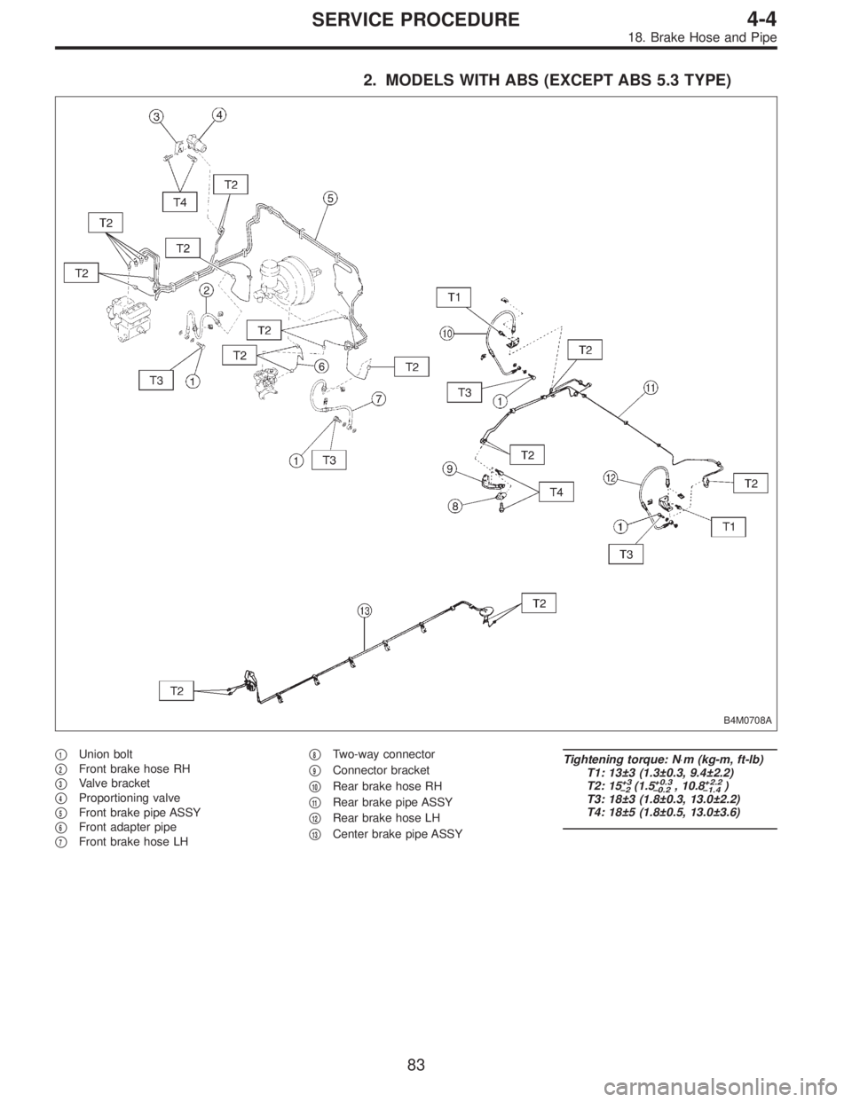
2. MODELS WITH ABS (EXCEPT ABS 5.3 TYPE)
B4M0708A
�1Union bolt
�
2Front brake hose RH
�
3Valve bracket
�
4Proportioning valve
�
5Front brake pipe ASSY
�
6Front adapter pipe
�
7Front brake hose LH�
8Two-way connector
�
9Connector bracket
�
10Rear brake hose RH
�
11Rear brake pipe ASSY
�
12Rear brake hose LH
�
13Center brake pipe ASSY
Tightening torque: N⋅m (kg-m, ft-lb)
T1: 13±3 (1.3±0.3, 9.4±2.2)
T2: 15
+3
�2(1.5+0.3
�0.2, 10.8+2.2
�1.4)
T3: 18±3 (1.8±0.3, 13.0±2.2)
T4: 18±5 (1.8±0.5, 13.0±3.6)
83
4-4SERVICE PROCEDURE
18. Brake Hose and Pipe
Page 1293 of 2890
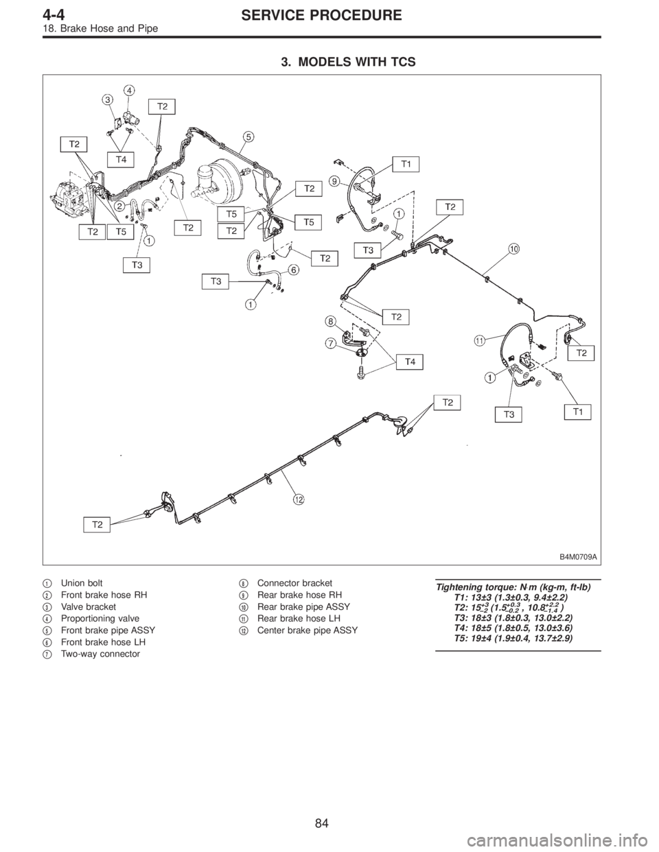
3. MODELS WITH TCS
B4M0709A
�1Union bolt
�
2Front brake hose RH
�
3Valve bracket
�
4Proportioning valve
�
5Front brake pipe ASSY
�
6Front brake hose LH
�
7Two-way connector�
8Connector bracket
�
9Rear brake hose RH
�
10Rear brake pipe ASSY
�
11Rear brake hose LH
�
12Center brake pipe ASSY
Tightening torque: N⋅m (kg-m, ft-lb)
T1: 13±3 (1.3±0.3, 9.4±2.2)
T2: 15
+3
�2(1.5+0.3
�0.2, 10.8+2.2
�1.4)
T3: 18±3 (1.8±0.3, 13.0±2.2)
T4: 18±5 (1.8±0.5, 13.0±3.6)
T5: 19±4 (1.9±0.4, 13.7±2.9)
84
4-4SERVICE PROCEDURE
18. Brake Hose and Pipe
Page 1294 of 2890
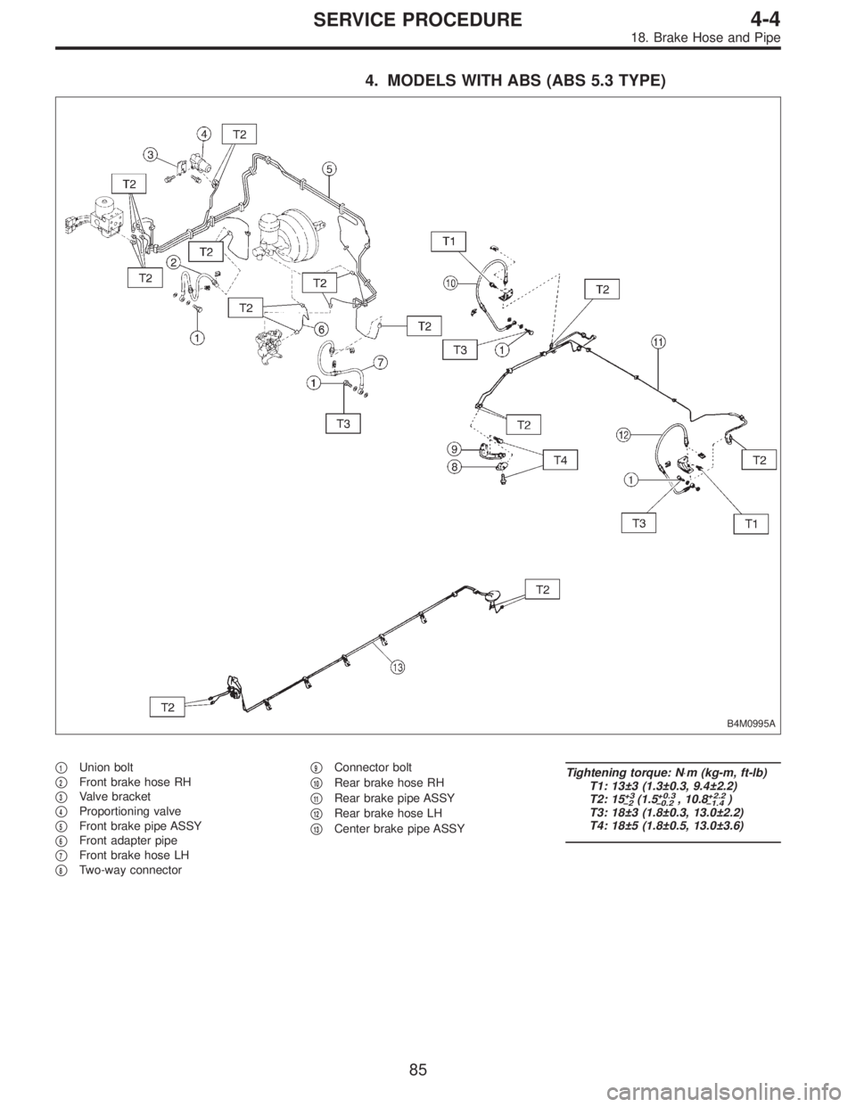
4. MODELS WITH ABS (ABS 5.3 TYPE)
B4M0995A
�1Union bolt
�
2Front brake hose RH
�
3Valve bracket
�
4Proportioning valve
�
5Front brake pipe ASSY
�
6Front adapter pipe
�
7Front brake hose LH
�
8Two-way connector�
9Connector bolt
�
10Rear brake hose RH
�
11Rear brake pipe ASSY
�
12Rear brake hose LH
�
13Center brake pipe ASSY
Tightening torque: N⋅m (kg-m, ft-lb)
T1: 13±3 (1.3±0.3, 9.4±2.2)
T2: 15
+3
�2(1.5+0.3
�0.2, 10.8+2.2
�1.4)
T3: 18±3 (1.8±0.3, 13.0±2.2)
T4: 18±5 (1.8±0.5, 13.0±3.6)
85
4-4SERVICE PROCEDURE
18. Brake Hose and Pipe
 When the speed of at least one wheel reaches 10 km/h
(6 MPH), the operation is returned to the normal control
mode.
2) When L terminal is separated")
 Install relay box cover on hydraulic unit.
2) Install hydraulic unit to bracket.
Tightening torque:
18±5 N⋅m (1.8±0.5 kg-m, 13.0±3.6 ft-lb)
3) Tighten bracket and motor")
 Install relay box cover on hydraulic unit.
2) Install hydraulic unit to bracket.
Tightening torque:
18±5 N⋅m (1.8±0.5 kg-m, 13.0±3.6 ft-lb)
3) Tighten bracket and motor")