Page 1655 of 2890
, 100 minutes (AT)
Cold cranking ampere 430 amperes (MT), 490 amperes (AT)
Fuse10 A, 15 A, 20 A
Combination
meterSpeedometer")
1. Body Electrical
A: SPECIFICATIONS
BatteryReserve capacity 82 minutes (MT), 100 minutes (AT)
Cold cranking ampere 430 amperes (MT), 490 amperes (AT)
Fuse10 A, 15 A, 20 A
Combination
meterSpeedometer Electric pulse type
Tachometer Electric impulse type
Water temperature gauge Thermistor cross coil type
Fuel gauge Resistance cross coil type
Charge indicator light 12 V—1.4 W
Brake fluid level warning/parking brake indicator light 12 V—1.4 W
AT oil temperature warning light (AWD only) 12 V—1.4 W
A.B.S. warning light 12 V—1.4 W
CHECK ENGINE warning light
(Malfunction indicator lamp)12 V—1.4 W
Oil pressure warning light 12 V—1.4 W
AIRBAG system warning light 12 V—1.4 W
Low fuel warning light 12 V—3W
FWD indicator light 12 V—1.4 W
TCS warning light 12 V—1.4 W
TCS indicator light 12 V—1.4 W
Turn signal indicator light 12 V—1.4 W (2 pieces)
Seat belt warning light 12 V—1.4 W
Door open warning light 12 V—1.4 W
Headlight beam indicator light 12 V—1.4 W
Meter illumination light12 V—3 W (2 pieces)
12 V—3.4 W (4 pieces)
Headlight 12 V—60/55 W (Halogen)
Front clearance light 12 V—5W
Turn signal lightFront 12 V—21 W
Rear 12 V—21 W
Tail/Stop light 12 V—5/21 W
Back-up light 12 V—21 W
High-mount stop light12 V—18 W (SEDAN), 12 V—13 W
(WAGON)
License plate light 12 V—5W
Room light 12 V—8W
Trunk room light (SEDAN) 12 V—5W
Luggage room light (WAGON) 12 V—5W
Spot light 12 V—8 W (2 pieces)
Glove box light 12 V—3.4 W
Ash tray illumination light 12 V—1.7 W
Selector lever illumination light (AT model) 12 V—1.7 W
2
6-2SPECIFICATIONS
1. Body Electrical
Page 1695 of 2890
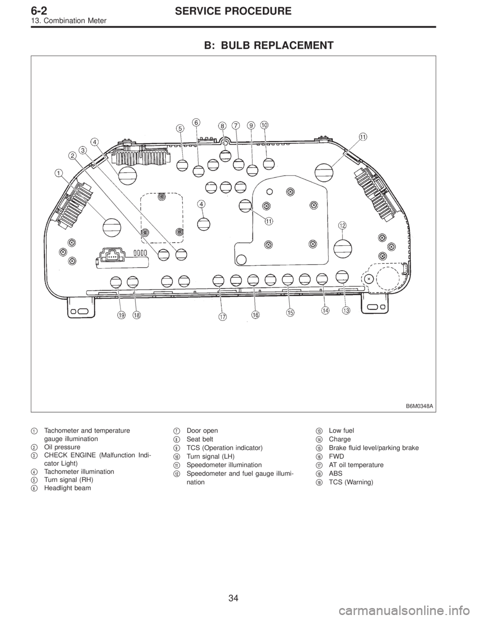
B: BULB REPLACEMENT
B6M0348A
�1Tachometer and temperature
gauge illumination
�
2Oil pressure
�
3CHECK ENGINE (Malfunction Indi-
cator Light)
�
4Tachometer illumination
�
5Turn signal (RH)
�
6Headlight beam�
7Door open
�
8Seat belt
�
9TCS (Operation indicator)
�
10Turn signal (LH)
�
11Speedometer illumination
�
12Speedometer and fuel gauge illumi-
nation�
13Low fuel
�
14Charge
�
15Brake fluid level/parking brake
�
16FWD
�
17AT oil temperature
�
18ABS
�
19TCS (Warning)
34
6-2SERVICE PROCEDURE
13. Combination Meter
Page 1708 of 2890
B6M0144A
3. SUNROOF RELAY
Check continuity between terminals as indicated in table
below, when battery voltage is applied between terminals
No. 1 and No. 3.
When current flows. Between terminals
No. 2 and No. 4Continuity exists.
When current does not flow. Between terminals
No. 2 and No. 4Continuity does not
exist.
Between terminals
No. 1 and No. 3Continuity exists.
B6M0354
20. Radio, Speaker and Antenna
A: REMOVAL AND INSTALLATION
1. RADIO BODY
1) Remove hand brake cover.
2) Remove console cover.
3) Remove screws which secure center panel. Remove
center panel.
B6M0355
4) Remove fitting screws, and slightly pull radio out of
instrument panel.
5) Disconnect connectors and antenna feeder cord.
B6M0146
2. FRONT SPEAKER
1) Remove gusset speaker from behind the rearview mir-
ror while disconnecting connector.
2) Remove door trim panel.
45
6-2SERVICE PROCEDURE
19. Sunroof - 20. Radio, Speaker and Antenna
Page 1709 of 2890
B6M0144A
3. SUNROOF RELAY
Check continuity between terminals as indicated in table
below, when battery voltage is applied between terminals
No. 1 and No. 3.
When current flows. Between terminals
No. 2 and No. 4Continuity exists.
When current does not flow. Between terminals
No. 2 and No. 4Continuity does not
exist.
Between terminals
No. 1 and No. 3Continuity exists.
B6M0354
20. Radio, Speaker and Antenna
A: REMOVAL AND INSTALLATION
1. RADIO BODY
1) Remove hand brake cover.
2) Remove console cover.
3) Remove screws which secure center panel. Remove
center panel.
B6M0355
4) Remove fitting screws, and slightly pull radio out of
instrument panel.
5) Disconnect connectors and antenna feeder cord.
B6M0146
2. FRONT SPEAKER
1) Remove gusset speaker from behind the rearview mir-
ror while disconnecting connector.
2) Remove door trim panel.
45
6-2SERVICE PROCEDURE
19. Sunroof - 20. Radio, Speaker and Antenna
Page 1713 of 2890
B6M0358
3) Remove nuts which secure actuator.
4) Remove actuator while disconnecting vacuum hose.
Tightening torque:
7.4±1.5 N⋅m (0.75±0.15 kg-m, 5.4±1.1 ft-lb)
B6M0359A
4. VACUUM PUMP AND VALVES
1) Disconnect connector from vacuum pump.
2) Remove bolts which secure vacuum pump.
3) Remove A/C receiver/drier bracket.
4) Remove vacuum pump while disconnecting vacuum
hose.
Tightening torque:
7.4±1.5 N⋅m (0.75±0.15 kg-m, 5.4±1.1 ft-lb)
5. STOP AND BRAKE SWITCH
Refer to 4-5 [C100] (MT) or 4-5 [C200] (AT) as for removal
and installation of stop and brake switch.
6. CLUTCH SWITCH (MT)
Refer to 4-5 [C100] as for removal and installation of clutch
switch.
7. INHIBITOR SWITCH (AT)
Refer to 3-2 [W4A3] as for removal and installation of
inhibitor switch.
G6M0095
8. CRUISE CONTROL MODULE
1) Disconnect battery ground cable.
B3M0377A
2) Remove lower cover and then disconnect connector.
49
6-2SERVICE PROCEDURE
21. Cruise Control
Page 1731 of 2890
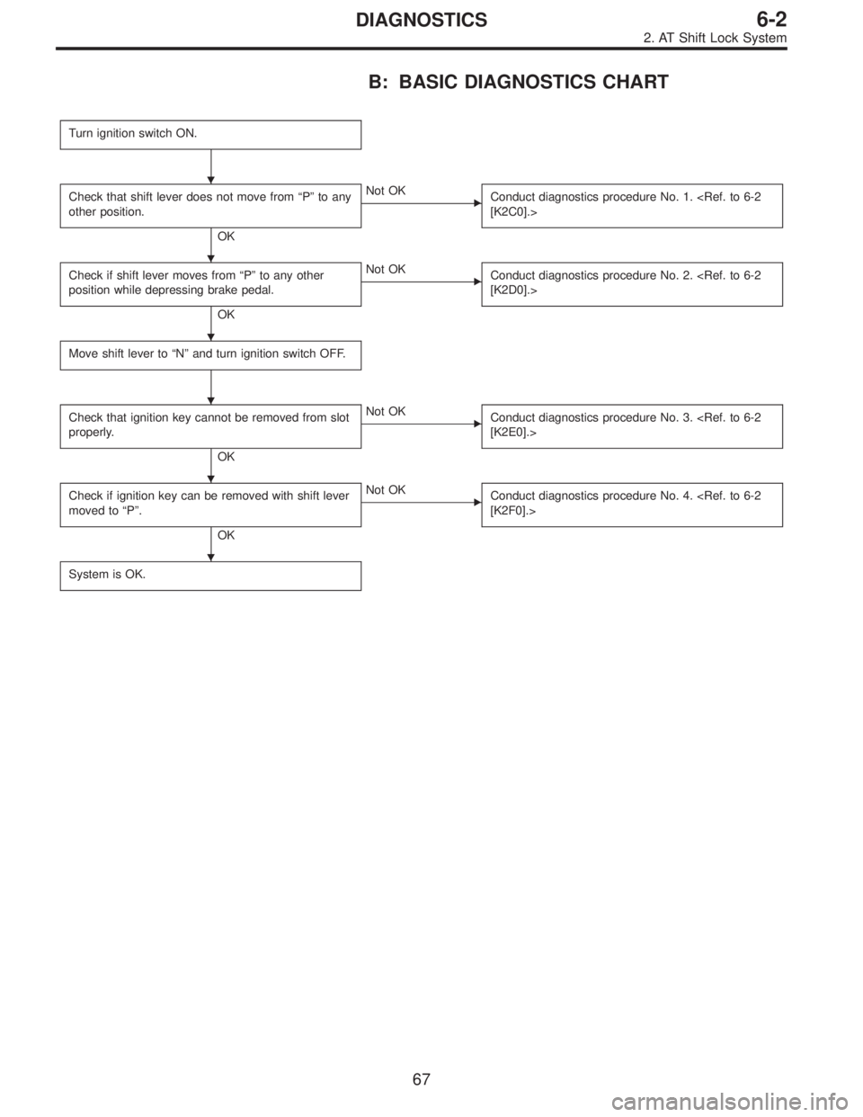
B: BASIC DIAGNOSTICS CHART
Turn ignition switch ON.
Check that shift lever does not move from“P”to any
other position.
OK
�Not OK
Conduct diagnostics procedure No. 1.
[K2C0].>
Check if shift lever moves from“P”to any other
position while depressing brake pedal.
OK
�Not OK
Conduct diagnostics procedure No. 2.
[K2D0].>
Move shift lever to“N”and turn ignition switch OFF.
Check that ignition key cannot be removed from slot
properly.
OK
�Not OK
Conduct diagnostics procedure No. 3.
[K2E0].>
Check if ignition key can be removed with shift lever
moved to“P”.
OK
�Not OK
Conduct diagnostics procedure No. 4.
[K2F0].>
System is OK.
�
�
�
�
�
�
67
6-2DIAGNOSTICS
2. AT Shift Lock System
Page 1732 of 2890
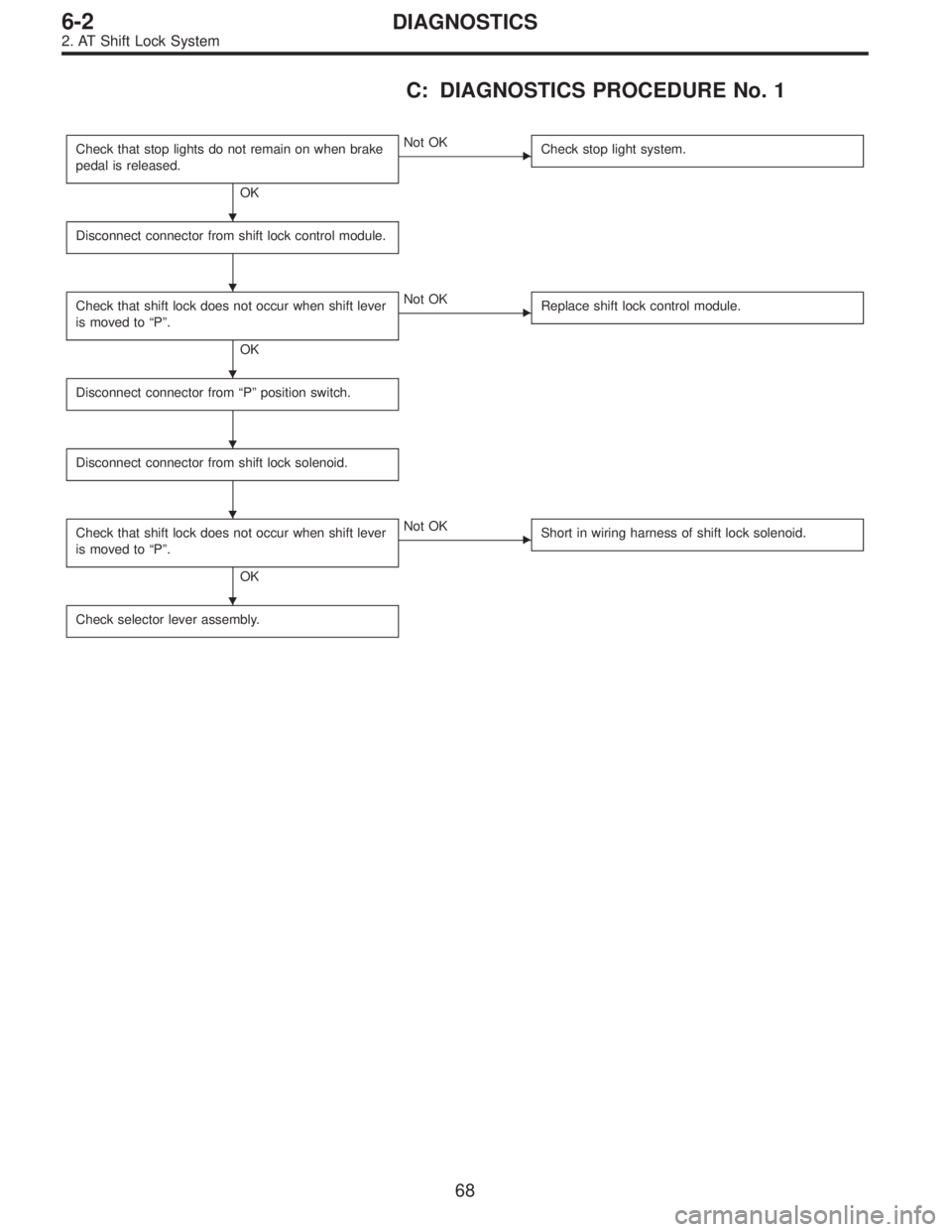
C: DIAGNOSTICS PROCEDURE No. 1
Check that stop lights do not remain on when brake
pedal is released.
OK
�Not OK
Check stop light system.
Disconnect connector from shift lock control module.
Check that shift lock does not occur when shift lever
is moved to“P”.
OK
�Not OK
Replace shift lock control module.
Disconnect connector from“P”position switch.
Disconnect connector from shift lock solenoid.
Check that shift lock does not occur when shift lever
is moved to“P”.
OK
�Not OK
Short in wiring harness of shift lock solenoid.
Check selector lever assembly.
�
�
�
�
�
�
68
6-2DIAGNOSTICS
2. AT Shift Lock System
Page 1733 of 2890

Check if stop light comes on when brake pedal is
depressed.
OK
�Not OK
Check stop light system.
Check if voltage between shift lock contro")
D: DIAGNOSTICS PROCEDURE No. 2 (SHIFT
LOCK DOES NOT RELEASE.)
Check if stop light comes on when brake pedal is
depressed.
OK
�Not OK
Check stop light system.
Check if voltage between shift lock control module
terminal No. 4 and body is at least 10 V when brake
pedal is depressed.
OK
�Not OK
Repair or replace wiring harness or faulty connector
between stop light switch and shift lock control
module.
Check if voltage between shift lock control module
terminal No. 1 and body is at least 10 V when
ignition switch is turned ON.
OK
�Not OK
Check fuse.
Repair or replace wiring harness or faulty connector
between ignition switch and shift lock control
module.
Turn ignition switch OFF.
Disconnect connector from shift lock control module.
Check if continuity exists between terminal No. 2 of
shift lock control module connector and body when
shift lever is set at“P”.
OK
�Not OK
Check inhibitor switch or repair wiring harness.
Check if continuity exists between terminal No. 5 of
shift lock control module connector and body when
shift lever is set at“P”.
OK
�Not OK
Check“P”position switch or repair wiring harness.
Measure resistance between terminal No. 1 of shift
lock control module connector and body.
Resistance is less than 20Ω.
OK
�Not OK
Shift lock solenoid circuit is shorted. Repair or
replace wiring harness or faulty connector between
shift lock solenoid and shift lock control module.
Resistance is at least 10Ω.
OK
�Not OK
Shift lock solenoid is shorted or poorly grounded.
* After repairs, recheck solenoid operation.
If still faulty, replace shift lock control module.
Check if resistance between terminal No. 10 of shift
lock control module connector and body is less than
10Ω.
OK
�Not OK
Shift lock control module ground circuit open or poor
connector contact.
Replace shift lock control module.
�
�
�
�
�
�
�
�
�
�
69
6-2DIAGNOSTICS
2. AT Shift Lock System


 Remove nuts which secure actuator.
4) Remove actuator while disconnecting vacuum hose.
Tightening torque:
7.4±1.5 N⋅m (0.75±0.15 kg-m, 5.4±1.1 ft-lb)
B6M0359A
4. VACUUM PUMP AND VALVES")