Page 2054 of 2890
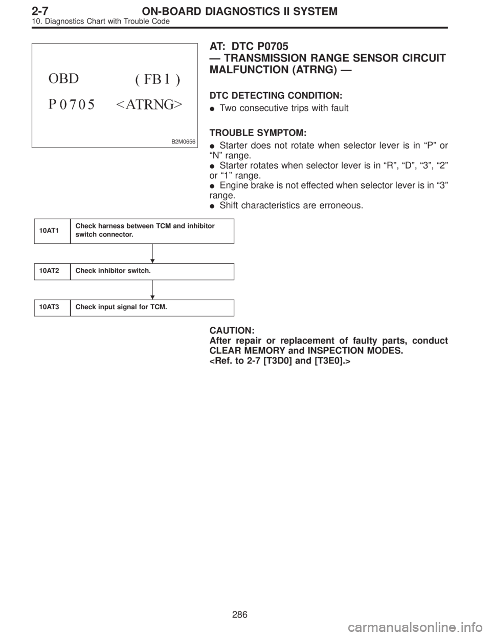
B2M0656
AT: DTC P0705
—TRANSMISSION RANGE SENSOR CIRCUIT
MALFUNCTION (ATRNG)—
DTC DETECTING CONDITION:
�Two consecutive trips with fault
TROUBLE SYMPTOM:
�Starter does not rotate when selector lever is in“P”or
“N”range.
�Starter rotates when selector lever is in“R”,“D”,“3”,“2”
or“1”range.
�Engine brake is not effected when selector lever is in“3”
range.
�Shift characteristics are erroneous.
10AT1Check harness between TCM and inhibitor
switch connector.
10AT2Check inhibitor switch.
10AT3Check input signal for TCM.
CAUTION:
After repair or replacement of faulty parts, conduct
CLEAR MEMORY and INSPECTION MODES.
�
�
286
2-7ON-BOARD DIAGNOSTICS II SYSTEM
10. Diagnostics Chart with Trouble Code
Page 2064 of 2890
B2M0657
AX: DTC P0731
—GEAR 1 INCORRECT RATIO (ATGR1)—
B2M0658
AY: DTC P0732
—GEAR 2 INCORRECT RATIO (ATGR2)—
B2M0659
AZ: DTC P0733
—GEAR 3 INCORRECT RATIO (ATGR3)—
B2M0660
BA: DTC P0734
—GEAR 4 INCORRECT RATIO (ATGR4)—
DTC DETECTING CONDITION:
�Two consecutive trips with fault
TROUBLE SYMPTOM:
�Shift point too high or too low; engine brake not effected
in“3”range; excessive shift shock; excessive tight corner
“braking”
296
2-7ON-BOARD DIAGNOSTICS II SYSTEM
10. Diagnostics Chart with Trouble Code
Page 2068 of 2890
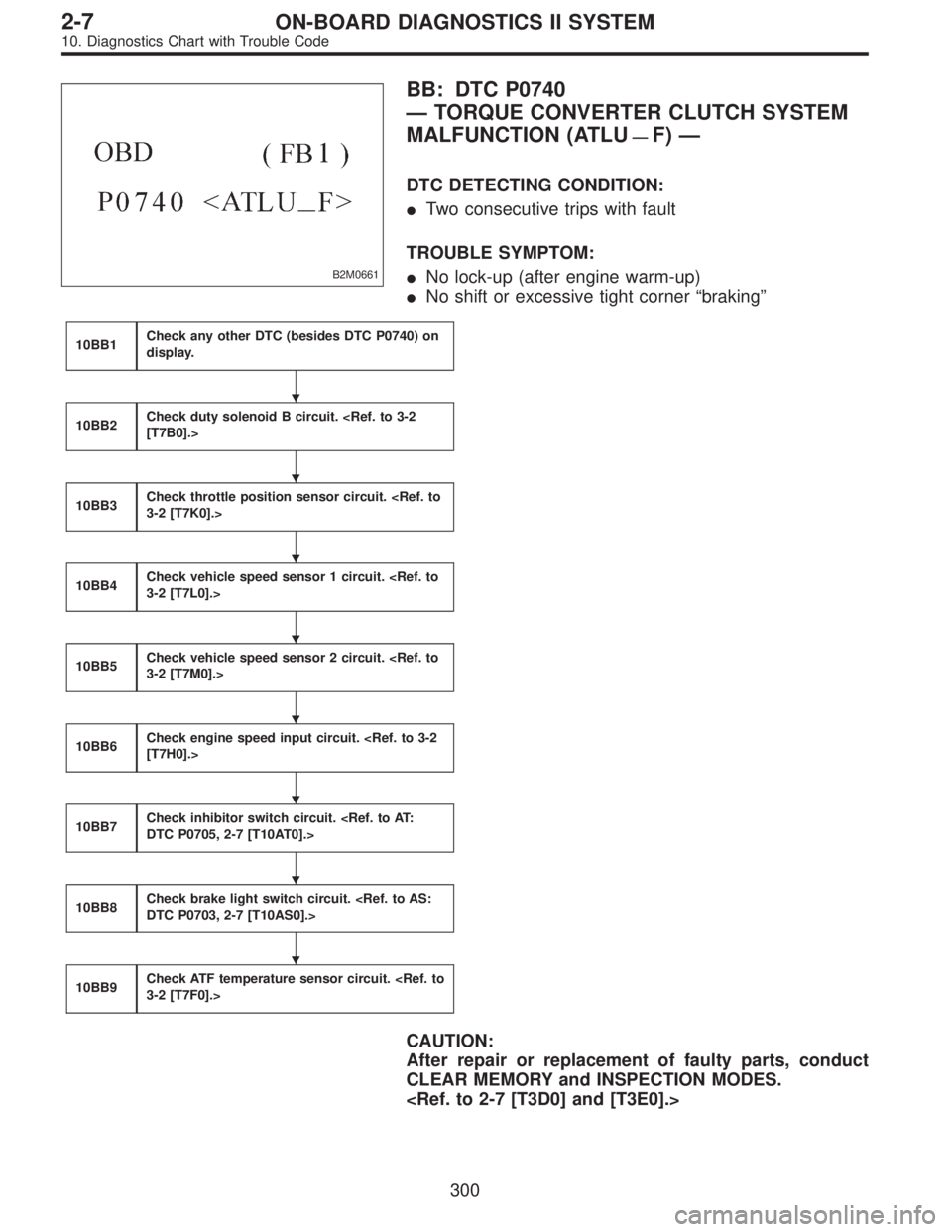
B2M0661
BB: DTC P0740
—TORQUE CONVERTER CLUTCH SYSTEM
MALFUNCTION (ATLU
—F)—
DTC DETECTING CONDITION:
�Two consecutive trips with fault
TROUBLE SYMPTOM:
�No lock-up (after engine warm-up)
�No shift or excessive tight corner“braking”
10BB1Check any other DTC (besides DTC P0740) on
display.
10BB2Check duty solenoid B circuit.
[T7B0].>
10BB3Check throttle position sensor circuit.
3-2 [T7K0].>
10BB4Check vehicle speed sensor 1 circuit.
3-2 [T7L0].>
10BB5Check vehicle speed sensor 2 circuit.
3-2 [T7M0].>
10BB6Check engine speed input circuit.
[T7H0].>
10BB7Check inhibitor switch circuit.
DTC P0705, 2-7 [T10AT0].>
10BB8Check brake light switch circuit.
DTC P0703, 2-7 [T10AS0].>
10BB9Check ATF temperature sensor circuit.
3-2 [T7F0].>
CAUTION:
After repair or replacement of faulty parts, conduct
CLEAR MEMORY and INSPECTION MODES.
�
�
�
�
�
�
�
�
300
2-7ON-BOARD DIAGNOSTICS II SYSTEM
10. Diagnostics Chart with Trouble Code
Page 2071 of 2890
![SUBARU LEGACY 1996 Service Repair Manual 10BB7
CHECK INHIBITOR SWITCH CIRCUIT.
: Is there any trouble in inhibitor switch cir-
cuit?
NOTE:
For the diagnostic procedure on inhibitor switch circuit,
refer to 2-7 [T10AT0].
: Repair or replace i](/manual-img/17/57433/w960_57433-2070.png "SUBARU LEGACY 1996 Service Repair Manual 10BB7
CHECK INHIBITOR SWITCH CIRCUIT.
: Is there any trouble in inhibitor switch cir-
cuit?
NOTE:
For the diagnostic procedure on inhibitor switch circuit,
refer to 2-7 [T10AT0].
: Repair or replace i")
10BB7
CHECK INHIBITOR SWITCH CIRCUIT.
: Is there any trouble in inhibitor switch cir-
cuit?
NOTE:
For the diagnostic procedure on inhibitor switch circuit,
refer to 2-7 [T10AT0].
: Repair or replace inhibitor switch circuit.
: Go to step10BB8.
10BB8
CHECK BRAKE LIGHT SWITCH CIRCUIT.
: Is there any trouble in brake light switch cir-
cuit?
NOTE:
For the diagnostic procedure on brake light switch circuit,
refer to 2-7 [T10AS0].
: Repair or replace brake light switch circuit.
: Go to step10BB9.
10BB9CHECK ATF TEMPERATURE SENSOR
CIRCUIT.
: Is there any trouble in ATF temperature sen-
sor circuit?
NOTE:
For the diagnostic procedure on ATF temperature sensor
circuit, refer to 3-2 [T7F0].
: Repair or replace ATF temperature sensor circuit.
: Go to next.
: Is there poor contact in TCM connector?
: Repair poor contact in TCM connector.
: Go to next.
: Is there any mechanical trouble in automatic
transmission?
: Repair or replace automatic transmission.
: Replace TCM.
303
2-7ON-BOARD DIAGNOSTICS II SYSTEM
10. Diagnostics Chart with Trouble Code
Page 2076 of 2890
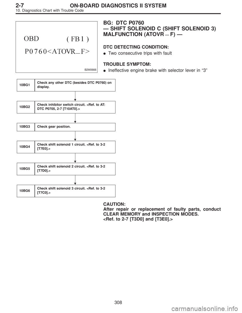
B2M0666
BG: DTC P0760
—SHIFT SOLENOID C (SHIFT SOLENOID 3)
MALFUNCTION (ATOVR
—F)—
DTC DETECTING CONDITION:
�Two consecutive trips with fault
TROUBLE SYMPTOM:
�Ineffective engine brake with selector lever in“3”
10BG1Check any other DTC (besides DTC P0760) on
display.
10BG2Check inhibitor switch circuit.
DTC P0705, 2-7 [T10AT0].>
10BG3Check gear position.
10BG4Check shift solenoid 1 circuit.
[T7E0].>
10BG5Check shift solenoid 2 circuit.
[T7D0].>
10BG6Check shift solenoid 3 circuit.
[T7C0].>
CAUTION:
After repair or replacement of faulty parts, conduct
CLEAR MEMORY and INSPECTION MODES.
�
�
�
�
�
308
2-7ON-BOARD DIAGNOSTICS II SYSTEM
10. Diagnostics Chart with Trouble Code
Page 2080 of 2890
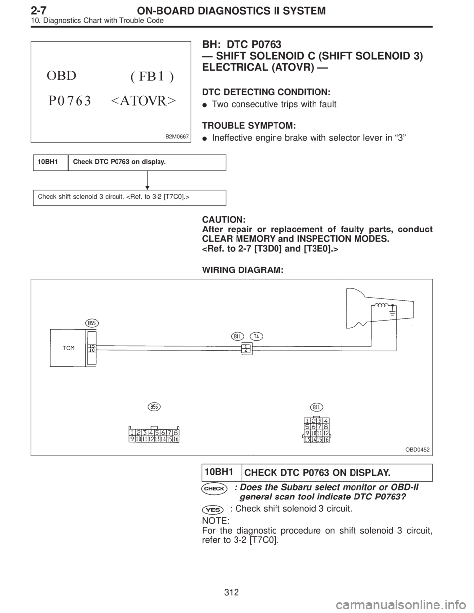
B2M0667
BH: DTC P0763
—SHIFT SOLENOID C (SHIFT SOLENOID 3)
ELECTRICAL (ATOVR)—
DTC DETECTING CONDITION:
�Two consecutive trips with fault
TROUBLE SYMPTOM:
�Ineffective engine brake with selector lever in“3”
10BH1Check DTC P0763 on display.
Check shift solenoid 3 circuit.
CAUTION:
After repair or replacement of faulty parts, conduct
CLEAR MEMORY and INSPECTION MODES.
WIRING DIAGRAM:
OBD0452
10BH1
CHECK DTC P0763 ON DISPLAY.
: Does the Subaru select monitor or OBD-II
general scan tool indicate DTC P0763?
: Check shift solenoid 3 circuit.
NOTE:
For the diagnostic procedure on shift solenoid 3 circuit,
refer to 3-2 [T7C0].
�
312
2-7ON-BOARD DIAGNOSTICS II SYSTEM
10. Diagnostics Chart with Trouble Code
Page 2129 of 2890
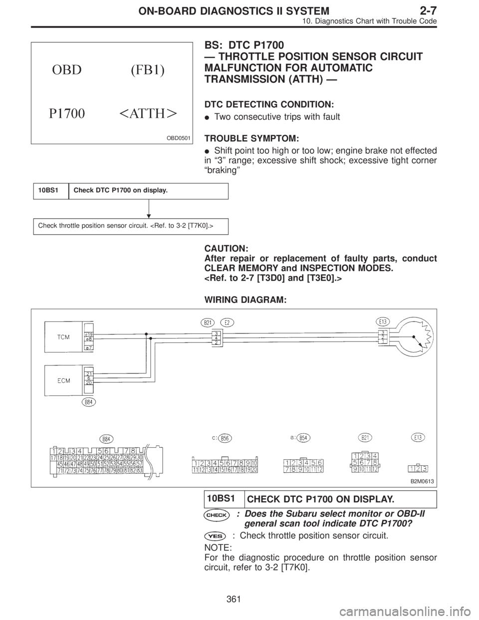
OBD0501
BS: DTC P1700
—THROTTLE POSITION SENSOR CIRCUIT
MALFUNCTION FOR AUTOMATIC
TRANSMISSION (ATTH)—
DTC DETECTING CONDITION:
�Two consecutive trips with fault
TROUBLE SYMPTOM:
�Shift point too high or too low; engine brake not effected
in“3”range; excessive shift shock; excessive tight corner
“braking”
10BS1Check DTC P1700 on display.
Check throttle position sensor circuit.
CAUTION:
After repair or replacement of faulty parts, conduct
CLEAR MEMORY and INSPECTION MODES.
WIRING DIAGRAM:
B2M0613
10BS1
CHECK DTC P1700 ON DISPLAY.
: Does the Subaru select monitor or OBD-II
general scan tool indicate DTC P1700?
: Check throttle position sensor circuit.
NOTE:
For the diagnostic procedure on throttle position sensor
circuit, refer to 3-2 [T7K0].
�
361
2-7ON-BOARD DIAGNOSTICS II SYSTEM
10. Diagnostics Chart with Trouble Code
Page 2147 of 2890
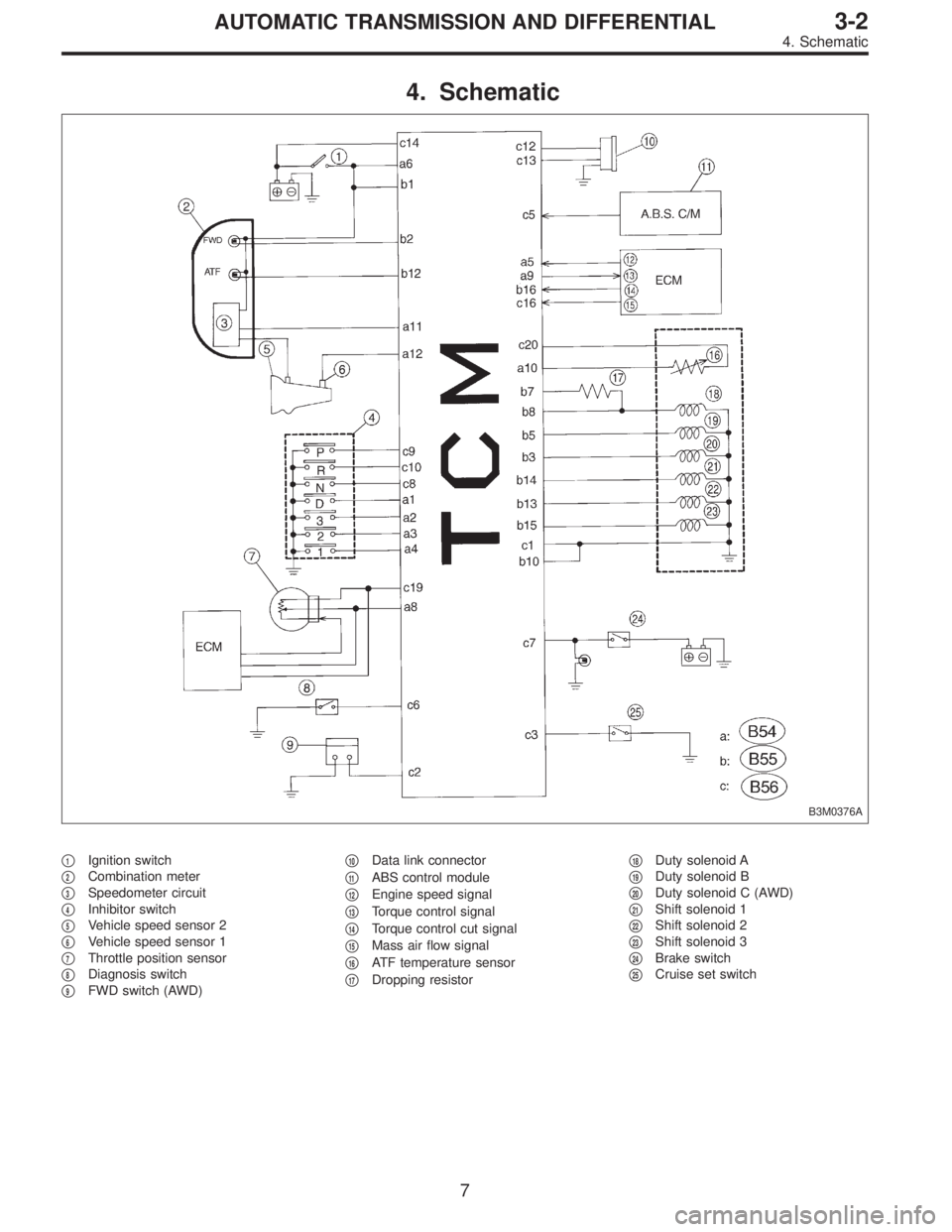
4. Schematic
B3M0376A
�1Ignition switch
�
2Combination meter
�
3Speedometer circuit
�
4Inhibitor switch
�
5Vehicle speed sensor 2
�
6Vehicle speed sensor 1
�
7Throttle position sensor
�
8Diagnosis switch
�
9FWD switch (AWD)�
10Data link connector
�
11ABS control module
�
12Engine speed signal
�
13Torque control signal
�
14Torque control cut signal
�
15Mass air flow signal
�
16ATF temperature sensor
�
17Dropping resistor�
18Duty solenoid A
�
19Duty solenoid B
�
20Duty solenoid C (AWD)
�
21Shift solenoid 1
�
22Shift solenoid 2
�
23Shift solenoid 3
�
24Brake switch
�
25Cruise set switch
7
3-2AUTOMATIC TRANSMISSION AND DIFFERENTIAL
4. Schematic
—
B2M0658
AY: DTC P0732
—GEAR 2 INCORRECT RATIO (ATGR2)—
B2M0659
AZ: DTC P0733
—GEAR 3 INCORRECT RATIO (ATGR3)—
B2M0660
BA: DTC P0734
�")