Page 2078 of 2543

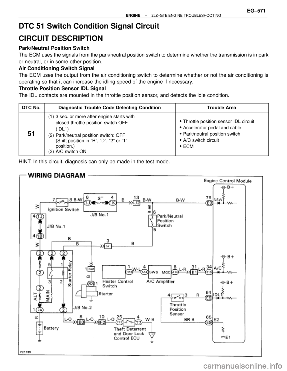
DTC 51 Switch Condition Signal Circuit
CIRCUIT DESCRIPTION
Park/Neutral Position Switch
The ECM uses the signals from the park/neutral position switch to determine whether the transmission is in park
or neutral, or in some other position.
Air Conditioning Switch Signal
The ECM uses the output from the air conditioning switch to determine whether or not the air conditioning is
operating so that it can increase the idling speed of the engine if necessary.
Throttle Position Sensor IDL Signal
The IDL contacts are mounted in the throttle position sensor, and detects the idle condition.
����� �����DTC No.������������������� �������������������Diagnostic Trouble Code Detecting Condition�������������� ��������������Trouble Area
����� �
���� �
���� �
���� �
���� �
���� �����
51
������������������� �
������������������ �
������������������ �
������������������ �
������������������ �
������������������ �������������������
(1) 3 sec. or more after engine starts with
closed throttle position switch OFF
(IDL1)
(2) Park/neutral position switch: OFF
(Shift position in ºRº, ºDº, º2º or º1º
position.)
(3) A/C switch ON�������������� �
������������� �
������������� �
������������� �
������������� �
������������� ��������������
�Throttle position sensor IDL circuit
�Accelerator pedal and cable
�Park/neutral position switch
�A/C switch circuit
�ECM
HINT: In this circuit, diagnosis can only be made in the test mode.
± ENGINE2JZ±GTE ENGINE TROUBLESHOOTINGEG±571
Page 2079 of 2543

INSPECTION PROCEDURE
PNP...Go to page EG±574.
(See page EG±514).
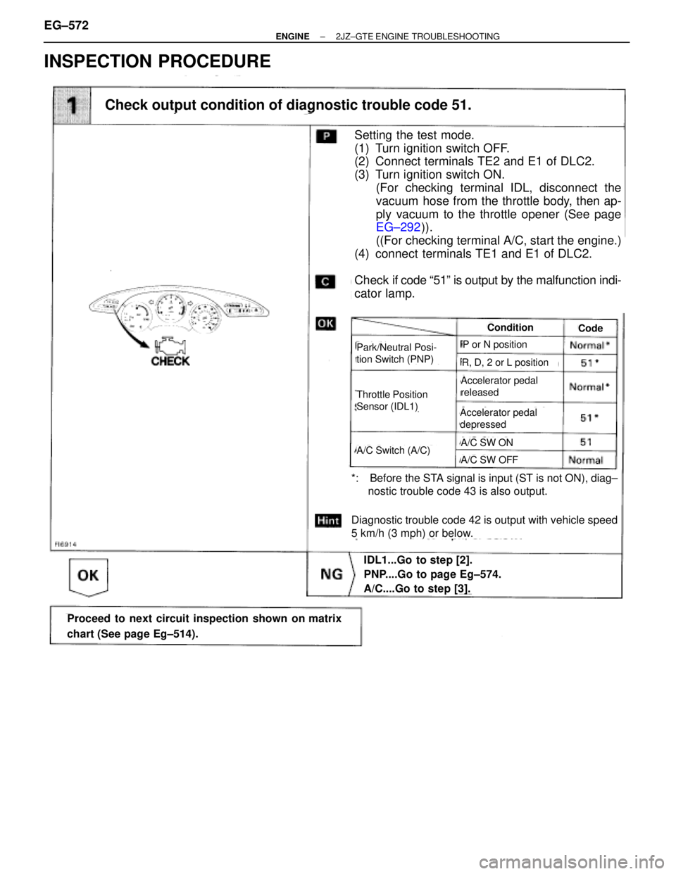
Setting the test mode.
(1) Turn ignition switch OFF.
(2) Connect terminals TE2 and E1 of DLC2.
(3) Turn ignition switch ON.
(For checking terminal IDL, disconnect the
vacuum hose from the throttle body, then ap-
ply vacuum to the throttle opener (See page
EG±292)).
((For checking terminal A/C, start the engine.)
(4) connect terminals TE1 and E1 of DLC2.
Check if code ª51º is output by the malfunction indi-
cator lamp.
*: Before the STA signal is input (ST is not ON), diag±
nostic trouble code 43 is also output.
Diagnostic trouble code 42 is output with vehicle speed
5 km/h (3 mph) or below.
Check output condition of diagnostic trouble code 51.
IDL1...Go to step [2].
PNP....Go to page Eg±574.
A/C....Go to step [3].
Proceed to next circuit inspection shown on matrix
chart (See page Eg±514).
Check output condition of diagnostic trouble code 51.
Throttle Position
Sensor (IDL1)
Condition
Park/Neutral Posi-
tion Switch (PNP)
Code
Accelerator pedal
released
Accelerator pedal
depressed
A/C SW ON
A/C SW OFFA/C Switch (A/C)
P or N position
R, D, 2 or L position
EG±572± ENGINE2JZ±GTE ENGINE TROUBLESHOOTING
Page 2080 of 2543
(See page EG±292)
(See page EG±510)
(See page AC±62)
(1) Remove throttle body.
(See page EG 291)
(2) Apply vacuum to throttle opener.
(See page EG±292)
Measure resistance between terminals 3 (IDL1)
and 4 (E2) of throttle position sensor connector.
Check throttle position sensor.
Check voltage between terminal A/C of engine control module connector and
body ground.
Adjust or replace throttle position sensor.
(See page EG±292)
Check and repair harness or connector between en-
gine control module and throttle position sensor.
(1) Connect SST (check harness ªAº).
(See page EG±510)
SST 09990±01000
(2) Start the engine.
Measure voltage between terminal A/C of engine
control module and body ground.
Check A/C compressor circuit.
(See page EG±62)
Check and replace engine control module.
± ENGINE2JZ±GTE ENGINE TROUBLESHOOTINGEG±573
Page 2081 of 2543
Park Neutral Position Switch Circuit
CIRCUIT DESCRIPTION
The park/neutral position switch goes on when the shift lever is in the N or P shift position. When it goes on the
terminal NSW of the ECM is grounded to body ground via the starter relay and theft deterrent ECU, thus the
terminal NSW voltage becomes 0 V. When the shift lever is in the D, 2, L or R position, the park/neutral position
switch goes off, so the voltage of ECM terminal NSW becomes positive battery voltage, the voltage of the ECM
internal power source.
If the shift lever is moved from the N position to the D position, this signal is used for air±fuel ratio correction
and for idle speed control (estimated control), etc.
When the park/neutral position switch is off, code º51º is output in the test mode diagnosis. (This is not abnor-
mal.)
EG±574± ENGINE2JZ±GTE ENGINE TROUBLESHOOTING
Page 2082 of 2543

INSPECTION PROCEDURE
HINT: This diagnosis chart is based on the premise that the engine is being cranked under normal conditions.
If the engine does not crank, proceed to the matrix chart of problem symptoms on page EG±514.
(See page EG±514).
(See page IN±30).
(See page AT2±101).
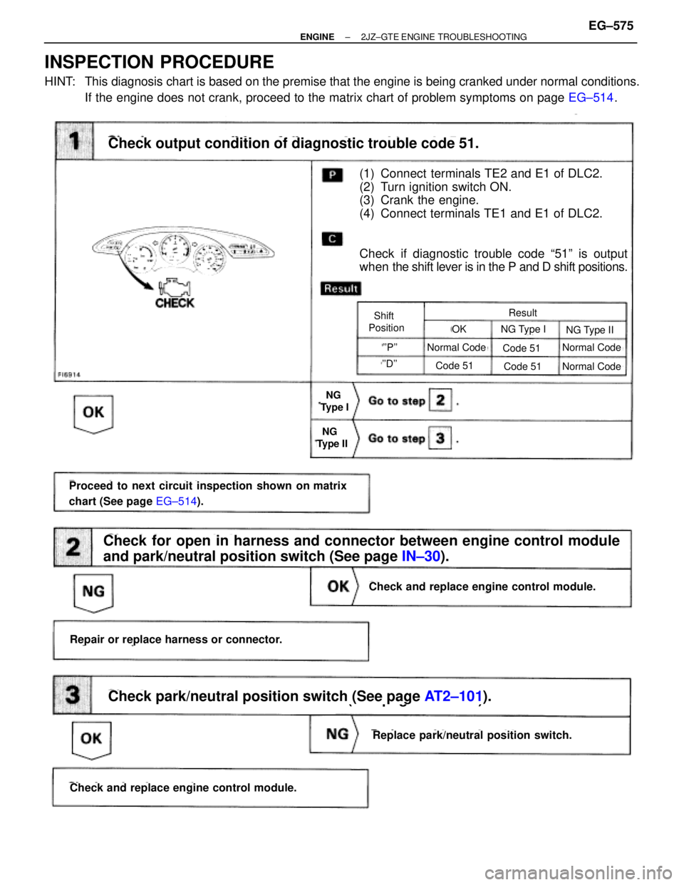
(1) Connect terminals TE2 and E1 of DLC2.
(2) Turn ignition switch ON.
(3) Crank the engine.
(4) Connect terminals TE1 and E1 of DLC2.
Check if diagnostic trouble code ª51º is output
when the shift lever is in the P and D shift positions.
Check output condition of diagnostic trouble code 51.
Check for open in harness and connector between engine control module
and park/neutral position switch (See page IN±30).
Check and replace engine control module.
Proceed to next circuit inspection shown on matrix
chart (See page EG±514).
Repair or replace harness or connector.
Replace park/neutral position switch.
Check and replace engine control module.
Check park/neutral position switch (See page AT2±101).
Shift
PositionResult
NG Type ING Type II
Normal CodeNormal Code
Normal CodeCode 51
Code 51
Code 51
''P''
''D''
OK
NG
Type I
NG
Type II
± ENGINE2JZ±GTE ENGINE TROUBLESHOOTINGEG±575
Page 2083 of 2543
ECM Power Source Circuit
CIRCUIT DESCRIPTION
When the ignition switch is turned on, battery volt-
age is applied to the terminal IGSW of the ECM,
and the main relay control circuit in the ECM sends
a signal to the terminal M±REL of the ECM, switch-
ing on the main relay. This signal causes current to
flow to the coil, closing the contacts of the main
relay and supplying power to the terminal + B of the
ECM.
If the ignition switch is turned off, the ECM contin-
ues to switch on the main relay for a maximum of
2 seconds for the initial setting of the IAC valve. EG±576
± ENGINE2JZ±GTE ENGINE TROUBLESHOOTING
Page 2084 of 2543
(See page EG±510)
(1) Connect SST (check harness ªAº).
(See page EG±510)
SST 09990±01000
(2) Turn ignition switch ON.
Measure voltage between terminal +B and E1 of
engine control module connector.
Voltage: 9 Ð 14 V
Check voltage between terminal +B and E1 of engine control module
connector.
Proceed to next circuit inspection shown on
matrix chart (See page EG±514).
Repair or replace harness or connector.
Check for open in harness and connector between terminal E1 of engine
control module and body ground (See page IN±30).
Turn ignition switch ON.
Measure voltage between terminal IGSW of en-
gine control module connector and body ground.
Voltage: 9 Ð 14 V
Check voltage between terminal IGSW of engine control module connector
and body ground.
INSPECTION PROCEDURE
± ENGINE2JZ±GTE ENGINE TROUBLESHOOTINGEG±577
Page 2085 of 2543
Check for short in the harness and all the compo-
nents connected to IGN fuse (See Electrical Wir-
ing Diagram).
Remove IGN fuse from J/B No.1.
Check continuity of IGN fuse.
Continuity
Check IGN fuse.
Check ignition switch.
(1) Remove finish lower panel and finish lower
panel LH.
(2) Remove heater to register duct No.2.
Check continuity between terminals.
Check and repair harness and connector between
battery and ignition switch, ignition switch and en-
gine control module.
Replace ignition switch.
Terminal
Switch position
LOCK
ACC
ON
START
continuity
EG±578± ENGINE2JZ±GTE ENGINE TROUBLESHOOTING