Page 2086 of 2543
Check for short in the harness and all the compo-
nents connected to EFI No.1 fuse (See Electrical
Wiring Diagram).
Turn ignition switch ON.
Measure voltage between terminal M±REL of en-
gine control module connector and body ground.
Voltage: 9 Ð 14 V
Check voltage between terminal M±REL of engine control module connector
and body ground
Check EFI No.1 Fuse.
Remove EFI No.1 fuse from R/B No.2.
Check continuity of EFI No.1 fuse.
Continuity
Check and replace engine control module.
± ENGINE2JZ±GTE ENGINE TROUBLESHOOTINGEG±579
Page 2087 of 2543
(See page IN±30).
Remove EFI main relay from R/B No.2.
Check continuity between terminals of EFI main
relay shown below.
Check EFI main relay.
(1) Apply battery positive voltage between termi±
nals 1 and 2.
(2) Check continuity between terminals 3 and 5.
Replace EFI main relay.
Repair or replace harness or connector.
Check for open and short in harness and connector between terminals
M±REL of engine control module and body ground (See page IN±30).
Check and repair harness or connector between EFI
No.1 fuse and battery.
Continuity
Continuity
Terminals 3 and 6
Terminals 3 and 5
Terminals 1 and 2 (Reference value 72 �)
Open
EG±580± ENGINE2JZ±GTE ENGINE TROUBLESHOOTING
Page 2088 of 2543
Back Up Power Source Circuit
CIRCUIT DESCRIPTION
Battery positive voltage is supplied to terminal BATT of the ECM even when the ignition switch is off for use by
the diagnostic trouble code memory and air±fuel ratio adaptive control value memory, etc.
± ENGINE2JZ±GTE ENGINE TROUBLESHOOTINGEG±581
Page 2089 of 2543
INSPECTION PROCEDURE
(See page EG±510)
Check and repair harness or connector between
engine control module and EFI No.1 fuse, EFI No.1
fuse and battery.
Remove EFI No.1 fuse from R/B No.2.
Check continuity of EFI No.1 fuse.
Continuity
Check EFI No.1 Fuse.
Check voltage between terminal BATT of engine control module connector
and body ground.
Connect SST (check harness ªAº).
See page EG±510)
SST 09990±01000
Measure voltage between terminal BATT of en-
gine control module connector and body ground.
Voltage: 9 Ð 14 V
Check for short in the harness and all the compo-
nents connected to EFI No.1 fuse (See attached
wiring diagram).
Are the diagnostic trouble codes still in the memory when the ignition switch
is turned OFF?
Check and replace engine control module.
Proceed to next circuit inspection shown on matrix
chart (See page EG±514).
EG±582± ENGINE2JZ±GTE ENGINE TROUBLESHOOTING
Page 2090 of 2543
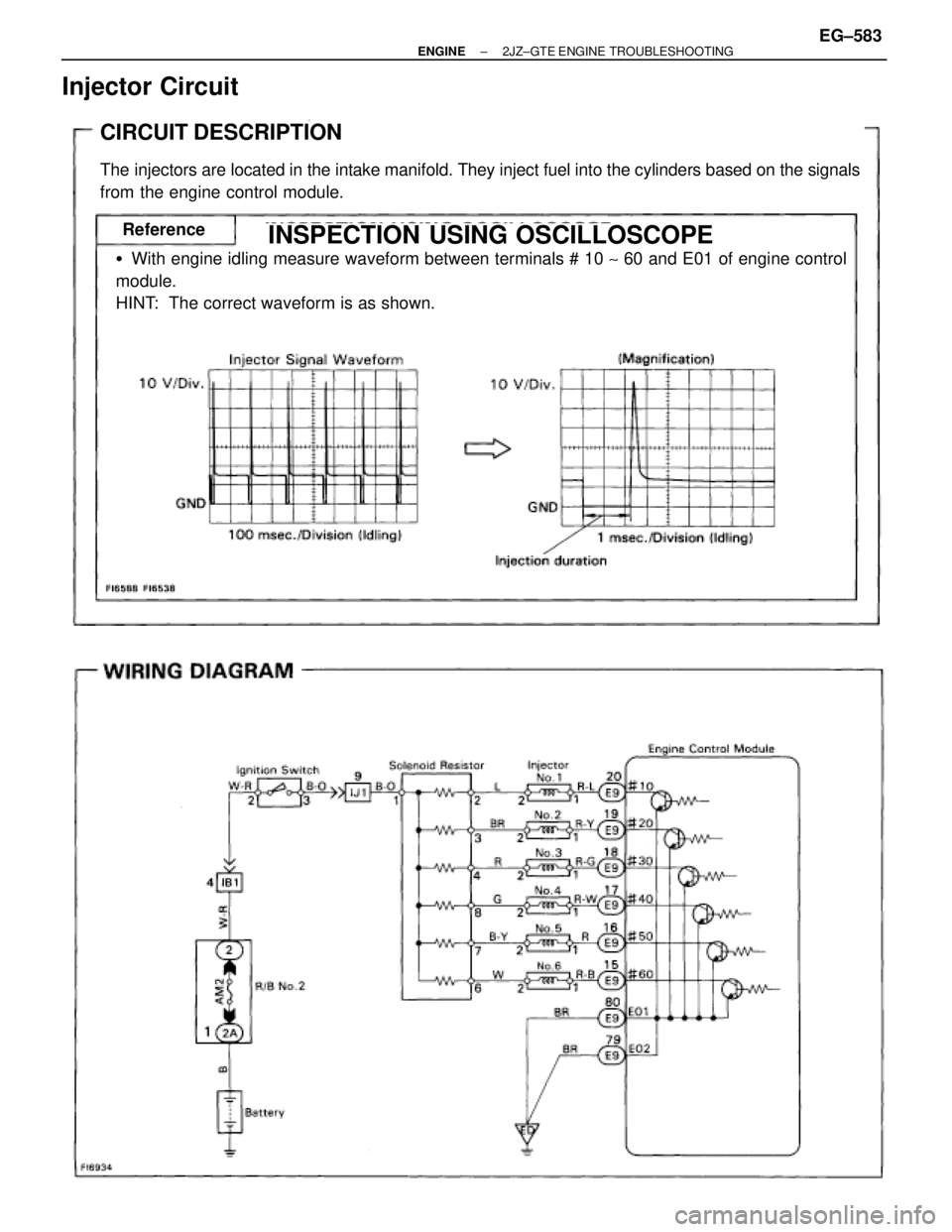
Injector Circuit
CIRCUIT DESCRIPTION
The injectors are located in the intake manifold. They inject fuel into the cylinders based on the signals
from the engine control module.
�With engine idling measure waveform between terminals # 10 ~ 60 and E01 of engine control
module.
HINT: The correct waveform is as shown.
INSPECTION USING OSCILLOSCOPEReferenceINSPECTION USING OSCILLOSCOPE
± ENGINE2JZ±GTE ENGINE TROUBLESHOOTINGEG±583
Page 2091 of 2543
INSPECTION PROCEDURE
Remove AM2 fuse from R/B No.2.
Check continuity of AM2 fuse.
Continuity
Check voltage between terminals # 10 ~ 60 of engine control module and
body ground.
Check AM2 fuse.
(1) Connect SST (check harness ªAº).
See page EG±510)
SST 09990±01000
(2) Turn ignition switch ON.
Measure voltage between terminals # 10 ~ 60 of en-
gine control module and body ground.
Voltage: 9 Ð 14 V
Check for short in the harness and all the components
connected to AM2 fuse.
EG±584± ENGINE2JZ±GTE ENGINE TROUBLESHOOTING
Page 2092 of 2543
.
Disconnect solenoid resistor connector.
Measure resistance between terminals 1 and 2
~
4, 6 ~ 8 of solenoid resistor connector.
Resistance: Approx. 6 � at 20°C (68°F)
Check res")
(See page IN±30).
Disconnect solenoid resistor connector.
Measure resistance between terminals 1 and 2
~
4, 6 ~ 8 of solenoid resistor connector.
Resistance: Approx. 6 � at 20°C (68°F)
Check resistance between terminals 1 and 2 ~ 4, 6 ~ 8 of solenoid resistor
connector.
Check for open in harness and connector between terminal E01, E02 of ECM
connector and body ground (See page IN±30).
Disconnect injector connector.
See page EG±273)
Measure resistance of injector.
Resistance: Approx. 1.95 � at 20°C (68°F)
Check injection volume of injector.
(See page EG±279)
�Injection volume
124
~ cm3/15 sec.
(7.6 Ð 8.8 cu in./15 sec.)
Difference between each injector:
Less than 10 cm
3 (0.6 cu in.)
�Leakage
Fuel drop: One drop or less per minute
Replace solenoid resistor.
Check and repair harness and connector
between engine control module and battery.
Repair or replace harness or connector.
Replace injector.
Check and replace engine control module.
Check injectors.
Check and replace engine control module.
± ENGINE2JZ±GTE ENGINE TROUBLESHOOTINGEG±585
Page 2093 of 2543
CIRCUIT DESCRIPTION
The IAC valve is situated on the intake air chamber In-
take air bypassing the throttle valve is directed to the
IAC valve through a passage.
A step motor is built into the IAC valve. It consists of 4
coils, a magnetic rotor, valve shaft and a valve.
When the current flows to the coils due to signals from
the ECM, the rotor turns and moves the valve shaft for-
ward or backward, changing the clearance between
the valve and the valve seat.
In this way the intake air volume bypassing the throttle
valve is regulated, controlling the engine speed.
There are 125 possible positions to which the valve can
be opened.
�With the engine idling measure wave forms
between terminals ISC1, ISC2, ISC3,
ISC4 and E01 of engine control module
when A/C switch ON or OFF.
HINT:
The correct waveforms are as shown.
INSPECTION USING OSCILLOSCOPEReference
IAC Valve Circuit
EG±586± ENGINE2JZ±GTE ENGINE TROUBLESHOOTING
.
Turn ignition switch ON.
Measure voltage between terminal M±REL of en-
gine contro")
.
Remove EFI main relay from R/B No.2.
Check continuity between terminals of EFI main
relay shown below.
Check EFI main relay.
(1) Apply battery positive voltage between termi±
nals")


Check and repair harness or connector between
engine control module and EFI No.1 fuse, EFI No.1
fuse and battery.
Remove EFI No.1 fuse from R/B No.2.
Check cont")
 Con")
