Page 2094 of 2543
± ENGINE2JZ±GTE ENGINE TROUBLESHOOTINGEG±587
Page 2095 of 2543
INSPECTION PROCEDURE
(See page IN±30).
(See page EG±514).
Disconnect IAC valve connector.
Measure resistance between terminals shown be-
low.
Check IAC valve.
Check for open and short in harness and connector between EFI main relay
and IAC valve, IAC valve and engine control module (See page IN±30).
Repair or replace harness or connector.
Remove IAC Valve.
(1) Connect the battery positive lead to terminals
5 (B1) and 2 (B2), and the negative lead to ter±
minals 4(S1)Ð1(S2)Ð6(S3)Ð3(S4) in that or
der.
(2) Connect the battery positive lead to terminals
5 (B1) and 2 (B2) and the negative lead to ter±
minals 3(S4)Ð6(S3)Ð1(S2)Ð4(S1) in that or
der.
(1) The valve moves in the closing direction
(2) The valve moves in the opening direction.
Replace IAC valve.
Proceed to next circuit inspection shown on ma-
trix chart (See page EG±514).
TerminalResistance
EG±588± ENGINE2JZ±GTE ENGINE TROUBLESHOOTING
Page 2096 of 2543
Turbo Control Circuit
CIRCUIT DESCRIPTION
[HINT]This turbocharger system has 3 control valves (Exhaust Bypass Valve, Exhaust Gas Control
Valve, Intake Air control Valve). Each valve is controlled by turbo pressure which is controlled
by VSV based on signals from ECM.
1.EXHAUST BYPASS VALVE
This valve controls the opening or closing of the exhaust bypass passage to ensure a smooth
transition from 1 turbo operation to 2 turbo operation.
2. EXHAUST GAS CONTROL VALVE
This valve controls the opening or closing of the No.2 exhaust passage in order to operate No.2
turbocharger.
3. INTAKE AIR CONTROL VALVE
This valve controls the opening or closing of the No.2 intake air passage in order to pass the
charged air from No.2 turbocharger.
± ENGINE2JZ±GTE ENGINE TROUBLESHOOTINGEG±589
Page 2097 of 2543
EG±590± ENGINE2JZ±GTE ENGINE TROUBLESHOOTING
Page 2098 of 2543
INSPECTION PROCEDURE
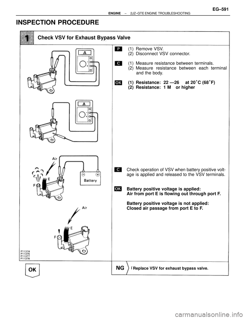
(1) Remove VSV.
(2) Disconnect VSV connector.
(1) Measure resistance between terminals.
(2) Measure resistance between each terminal
and the body.
(1) Resistance: 22 Ð26 � at 20°C (68°F)
(2) Resistance: 1 M� or higher
Check operation of VSV when battery positive volt-
age is applied and released to the VSV terminals.
Battery positive voltage is applied:
Air from port E is flowing out through port F.
Battery positive voltage is not applied:
Closed air passage from port E to F.
Check VSV for Exhaust Bypass Valve
Replace VSV for exhaust bypass valve.
± ENGINE2JZ±GTE ENGINE TROUBLESHOOTINGEG±591
Page 2099 of 2543
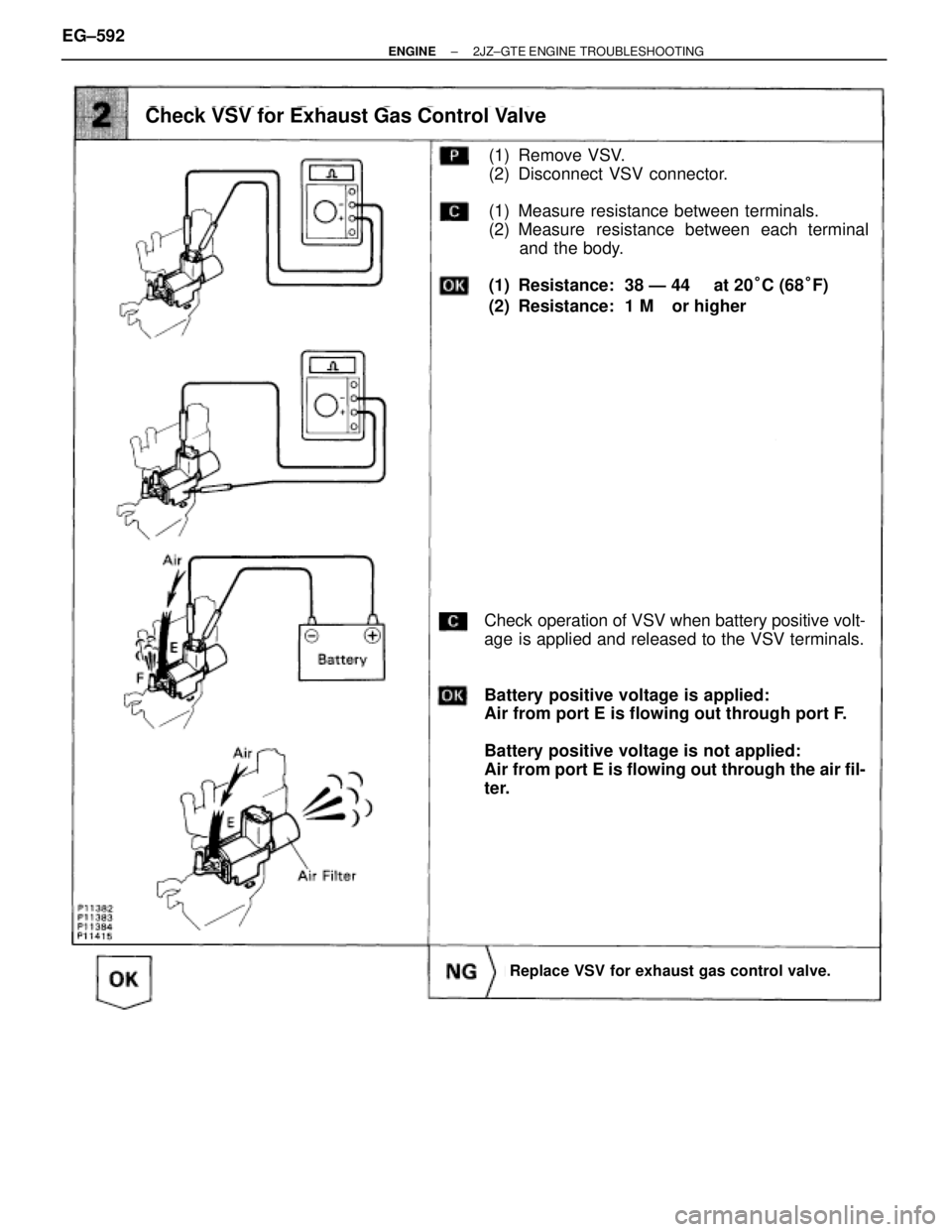
(1) Remove VSV.
(2) Disconnect VSV connector.
(1) Measure resistance between terminals.
(2) Measure resistance between each terminal
and the body.
(1) Resistance: 38 Ð 44 � at 20°C (68°F)
(2) Resistance: 1 M� or higher
Check operation of VSV when battery positive volt-
age is applied and released to the VSV terminals.
Battery positive voltage is applied:
Air from port E is flowing out through port F.
Battery positive voltage is not applied:
Air from port E is flowing out through the air fil-
ter.
Check VSV for Exhaust Gas Control Valve
Replace VSV for exhaust gas control valve.
EG±592± ENGINE2JZ±GTE ENGINE TROUBLESHOOTING
Page 2100 of 2543
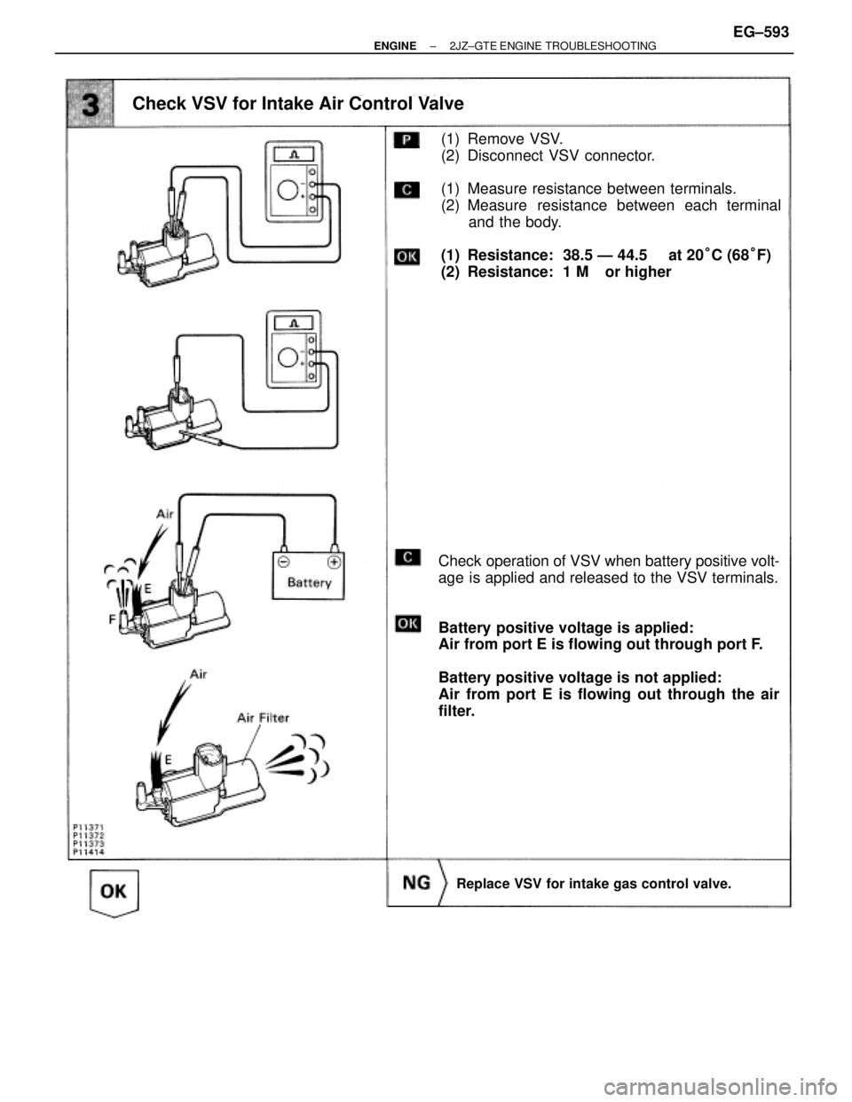
(1) Remove VSV.
(2) Disconnect VSV connector.
(1) Measure resistance between terminals.
(2) Measure resistance between each terminal
and the body.
(1) Resistance: 38.5 Ð 44.5 � at 20°C (68°F)
(2) Resistance: 1 M� or higher
Check operation of VSV when battery positive volt-
age is applied and released to the VSV terminals.
Battery positive voltage is applied:
Air from port E is flowing out through port F.
Battery positive voltage is not applied:
Air from port E is flowing out through the air
filter.
Check VSV for Intake Air Control Valve
Replace VSV for intake gas control valve.
± ENGINE2JZ±GTE ENGINE TROUBLESHOOTINGEG±593
Page 2101 of 2543
(See page EG±510)
(See page IN±30).
(1) Connect SST (check harness ªAº).
(See page EG±510)
(2) Turn ignition switch ON.
Measure voltage between terminal VSV1, VSV2,
VSV3 of engine control module connector and
body ground.
Voltage: 9 Ð 14 V
Check voltage between terminal VSV1, VSV2, VSV3 of engine control
module connector and body ground.
Check actuator. (See page EG±144, 158)
Repair or replace harness or connector.
Check for open and short in harness and connector between EFI main replay
and engine control module (See page IN±30).
Check and replace engine control module. EG±594
± ENGINE2JZ±GTE ENGINE TROUBLESHOOTING

.
(See page EG±514).
Disconnect IAC valve connector.
Measure resistance between terminals shown be-
low.
Check IAC valve.
Check for open and short in harness and")
![TOYOTA SUPRA 1995 Service Repair Manual Turbo Control Circuit
CIRCUIT DESCRIPTION
[HINT]This turbocharger system has 3 control valves (Exhaust Bypass Valve, Exhaust Gas Control
Valve, Intake Air control Valve). Each valve is controlled by t](/manual-img/14/57468/w960_57468-2095.png "TOYOTA SUPRA 1995 Service Repair Manual Turbo Control Circuit
CIRCUIT DESCRIPTION
[HINT]This turbocharger system has 3 control valves (Exhaust Bypass Valve, Exhaust Gas Control
Valve, Intake Air control Valve). Each valve is controlled by t")


(See page IN±30).
(1) Connect SST (check harness ªAº).
(See page EG±510)
(2) Turn ignition switch ON.
Measure voltage between terminal VSV1, VSV2,
VSV3 of engine control module")