Page 2046 of 2543
EG±583
IG±21
EG±33
EG±261
EG±568
EG±544
EG±530
EG±532
EG±9).
Check each circuit found to be a possible cause of trouble according to the results of the check in
Check each item found to be a possible cause of problem.
The numbers int he table below show the order in which the checks should be done.
Air leakage
Misfire
Fuel system
Injector circuit
Characteristics deviation
in engine coolant temp. sensor
Characteristics deviation
in intake air temp. sensor
Characteristics deviation in mass
air flow meter
Va l v e t i m i n g
Main heater oxygen sensor signal
continues at 5.0 VMain heater oxygen sensor
signal is normal
Check compression (See page EG±9).
Repair or replace.
Repair or replace.
Repair main heated oxygen sensor.
Check and replace engine control module.
Does malfunction disappear when a good main heated oxygen sensor is
installed?
± ENGINE2JZ±GTE ENGINE TROUBLESHOOTINGEG±539
Page 2047 of 2543

DTC 27 Sub Heated Oxygen Sensor Circuit
CIRCUIT DESCRIPTION
The sub heated oxygen sensor is installed on the exhaust pipe. Its construction and operation is the same as
the main heated oxygen sensor on page EG±525.
����� �
���� �����DTC No.���������������� �
��������������� ����������������Diagnostic Trouble Code Detecting Condition����������������� �
���������������� �����������������Trouble Area
����� �
���� �
���� �
���� �����
���������������� �
��������������� �
��������������� �
��������������� ����������������
(1) Open or short in heater circuit of sub
heated oxygen sensor for 0.5 sec. or more
����������������� �
���������������� �
���������������� �
���������������� �����������������
�Open or short in heater circuit of sub heated
oxygen sensor
�Sub heated oxygen sensor heater
�ECM
����� �
���� �
���� �
���� �
���� �
���� �
���� �
���� �
���� �����
27
���������������� �
��������������� �
��������������� �
��������������� �
��������������� �
��������������� �
��������������� �
��������������� �
��������������� ����������������
(2) Main heated oxygen sensor signal is 0.45 V
or more and sub heated oxygen sensor
signal is 0.45 V or less under conditions
(a) ~ (c):
(2 trip detection logic).*
(a) Engine coolant temp.: 805C (1765F)
or more
(b) Engine speed: 1,500 rpm or more
(c) Accel. pedal: Fully depressed for 2
sec. or more����������������� �
���������������� �
���������������� �
���������������� �
���������������� �
���������������� �
���������������� �
���������������� �
���������������� �����������������
�Open or short in sub heated oxygen sensor
circuit
�Sub heated oxygen sensor
�ECM
*: See page EG±503. EG±540
± ENGINE2JZ±GTE ENGINE TROUBLESHOOTING
Page 2048 of 2543

DIAGNOSTIC TROUBLE CODE DETECTION DRIVING PATTERN
Purpose of the driving pattern.
(a) To simulate diagnostic trouble code detecting condition after diagnostic trouble cod")
CIRCUIT DESCRIPTION (Cont'd)
DIAGNOSTIC TROUBLE CODE DETECTION DRIVING PATTERN
Purpose of the driving pattern.
(a) To simulate diagnostic trouble code detecting condition after diagnostic trouble code is recorded.
(b) To check that the malfunction is corrected when the repair is completed confirming that
diagnostic trouble code is no longer detected.
(1) Disconnect the EFI No.1 fuse (30A) for 10 sec. or more, with IG switch OFF.
Initiate test mode (Connect terminal TE2 and E1 of data link connector 2 with
IG switch OFF).
(2) Start the engine and warm up with all ACC switched OFF.
(3) Drive the vehicle at 80 ~ 88 km/h (50 ~ 55 mph) for 10 min. or more.
(4) Stop at a safe place and idle the engine for 2 min. or less.
(5) Accelerate to 96 km/h (60 mph) with the throttle valve fully open.
HINT: If a malfunction exists, the malfunction indicator lamp will light up during step (5).
NOTICE: If the conditions in this test are not strictly followed, detection of the malfunction
will not be possible.
Malfunction: Open or Short in Sub Heated Oxygen Sensor
± ENGINE2JZ±GTE ENGINE TROUBLESHOOTINGEG±541
Page 2049 of 2543
INSPECTION PROCEDURE
HINT: When other codes are output in addition to 27 at the same time, check the circuits for other codes first.
(See page EG±510)
(1) Connect SST (check harness ªAº).
(See page EG±510)
SST 09990±01000
(2) Turn ignition switch ON.
Measure voltage between terminal HT2 of
engine control module connector and body
ground.
Voltage: 9 Ð 14 V
Check voltage between terminal HT2 of engine control module connector
and body ground.
EG±542± ENGINE2JZ±GTE ENGINE TROUBLESHOOTING
Page 2050 of 2543
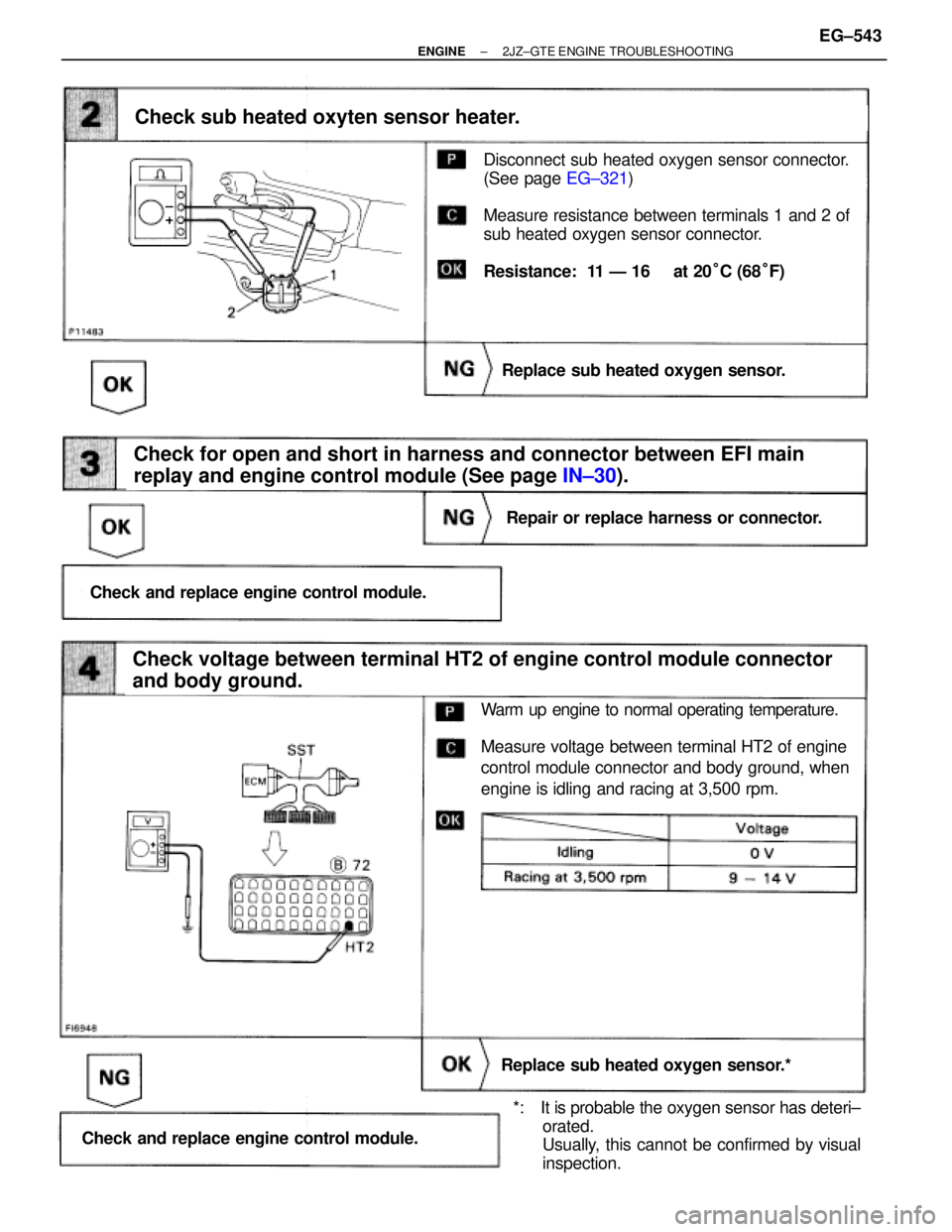
(See page EG±321)
Disconnect sub heated oxygen sensor connector.
(See page EG±321)
Measure resistance between terminals 1 and 2 of
sub heated oxygen sensor connector.
Resistance: 11 Ð 16 � at 20°C (68°F)
Check for open and short in harness and connector between EFI main
replay and engine control module (See page IN±30).
Check sub heated oxyten sensor heater.
Replace sub heated oxygen sensor.
Repair or replace harness or connector.
Check and replace engine control module.
Check voltage between terminal HT2 of engine control module connector
and body ground.
Replace sub heated oxygen sensor.*
Check and replace engine control module.
Warm up engine to normal operating temperature.
Measure voltage between terminal HT2 of engine
control module connector and body ground, when
engine is idling and racing at 3,500 rpm.
*: It is probable the oxygen sensor has deteri±
orated.
Usually, this cannot be confirmed by visual
inspection.
± ENGINE2JZ±GTE ENGINE TROUBLESHOOTINGEG±543
Page 2051 of 2543

DTC 31 Mass Air Flow Meter Circuit
CIRCUIT DESCRIPTION
The mass air flow meter is an air flow meter which uses a platinum hot wire. The hot wire air flow meter
works on the principle that when the electrically heated platinum hot wire is positioned inside the intake
air bypass, the intake air volume can be calculated according to the change in the hot wire temperature.
This change in temperature is measured by the thermistor at the rear of the hot wire. And feedback from
the circuit maintains the hot wire at a set temperature by controlling the current flowing through the hot
wire. This current flow is then measured as the output voltage of the air flow meter. The circuit is
constructed so that the platinum hot wire and the thermistor provide a bridge circuit, with the power transis-
tor controlled so that the potential of (A) or (B) remains equal to maintain the set temperature.
�Open or short in mass air flow master
circuit
�Mass air flow meter
�ECM
Open or short in mass air flow meter circuit for
3 sec. or more with engine speed less than
3,000 rpm
If the ECM detects diagnostic trouble code ª31º, it operates the fail safe function whereby the turbo
pressure sensor is used, making it possible to continue to drive the vehicle. EG±544
± ENGINE2JZ±GTE ENGINE TROUBLESHOOTING
Page 2052 of 2543
(See page IN±30).
(See page EG±510)(1) Connect SST (check harness ªAº).
(See page EG±510)
SST 09990±01000
(2) Start engine.
Measure voltage between terminals VG and E21 of
engine control module connector while engine rpm
at idling.
Voltage: 0.7 Ð 1.7 V
Check voltage between terminal 1 of mass air flow meter connector and
body ground.
Check voltage between terminals VG and E21 of engine control module
connector.
Check and replace engine control module
Check for open and short in harness and connector between engine
control module and mass air flow meter (See page IN±30).
Check and repair mass air flow meter power
source circuit.
Repair or replace harness or connector.
Replace mass air flow meter.
(1) Disconnect the mass air flow meter connector.
(2) Turn ignition switch ON.
Measure voltage between terminal 1 of mass air
flow meter connector and body ground.
Voltage: 9 Ð 14 V
INSPECTION PROCEDURE
± ENGINE2JZ±GTE ENGINE TROUBLESHOOTINGEG±545
Page 2053 of 2543
CIRCUIT DESCRIPTION
To control maximum turbocharging pressure the turbocharger system includes a waste gate valve con-
trolled by an actuator. The actuator is controlled by the manifold pressure which is duty controlled by the
VSV based on signals from the ECM.
If the ECM detects the below diagnosis conditions, it operates the fail safe function in which the ECM
stops fuel injection.
�Actuator (for waste gate valve)
�Short in VSV for waste gate valve circuit
�ECM
All conditions below are detected continuously
for 2 sec. or more:
(a) Manifold absolute pressure:
200 kPa (2.0 kgf/cm
2, 29 psi) or more
(b) Throttle valve opening angle:
20° or more
(c) Engine speed: 2,400 rpm or more
DTC 34 Turbo Pressure Malfunction
EG±546± ENGINE2JZ±GTE ENGINE TROUBLESHOOTING
.
Check each circuit found to be a possible cause of trouble according to the results of the check in
Check each item found to be a")

(1) Connect SST (check harness ªAº).
(See page")
.
(See page EG±510)(1) Connect SST (check harness ªAº).
(See page EG±510)
SST 09990±01000
(2) Start engine.
Measure voltage between terminals VG and E21 of
engine control module")
