Page 732 of 2543
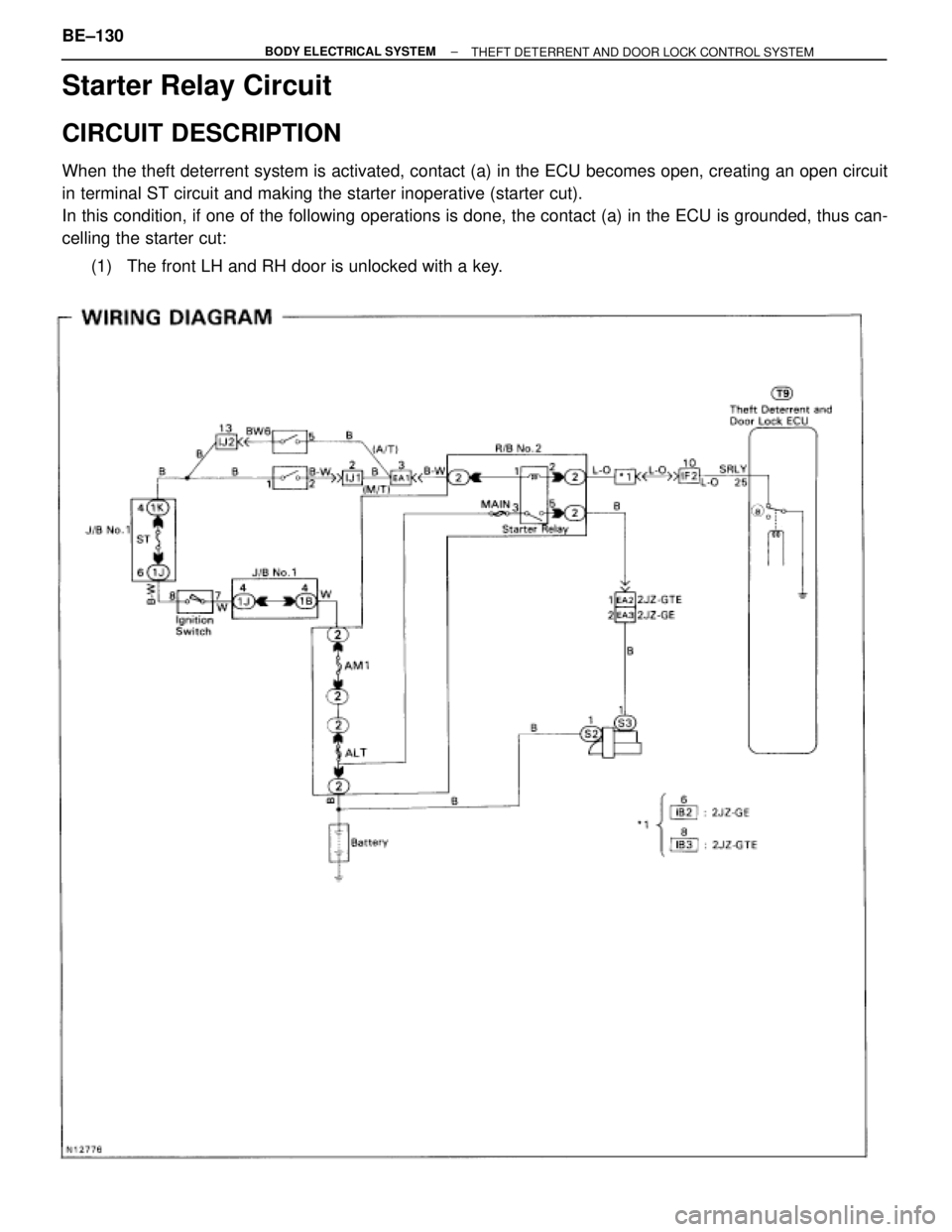
Starter Relay Circuit
CIRCUIT DESCRIPTION
When the theft deterrent system is activated, contact (a) in the ECU becomes open, creating an open circuit
in terminal ST circuit and making the starter inoperative (starter cut).
In this condition, if one of the following operations is done, the contact (a) in the ECU is grounded, thus can-
celling the starter cut:
(1) The front LH and RH door is unlocked with a key. BE±130
± BODY ELECTRICAL SYSTEM
THEFT DETERRENT AND DOOR LOCK CONTROL SYSTEM
Page 734 of 2543
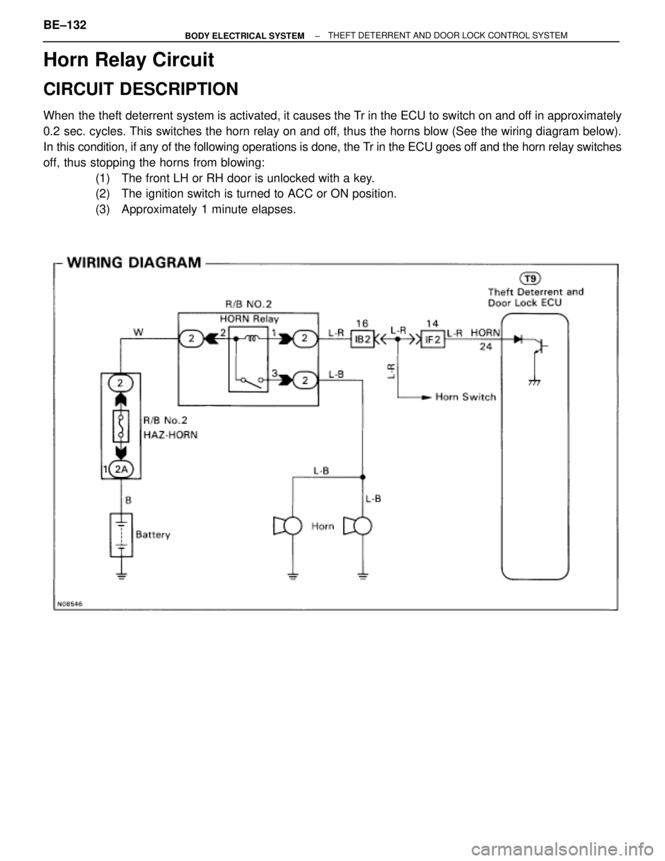
Horn Relay Circuit
CIRCUIT DESCRIPTION
When the theft deterrent system is activated, it causes the Tr in the ECU to switch on and off in approximately
0.2 sec. cycles. This switches the horn relay on and off, thus the horns blow (See the wiring diagram below).
In this condition, if any of the following operations is done, the Tr in the ECU goes off and the horn relay switches
off, thus stopping the horns from blowing:
(1) The front LH or RH door is unlocked with a key.
(2) The ignition switch is turned to ACC or ON position.
(3) Approximately 1 minute elapses.
BE±132± BODY ELECTRICAL SYSTEMTHEFT DETERRENT AND DOOR LOCK CONTROL SYSTEM
Page 735 of 2543
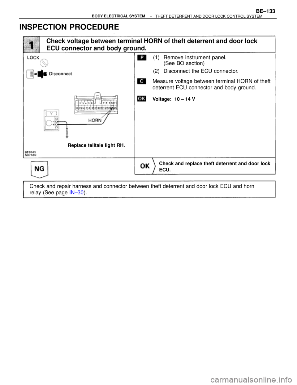
INSPECTION PROCEDURE
(See page IN±30).
Check and repair harness and connector between theft deterrent and door lock ECU and horn
relay (See page IN±30).
(1) Remove instrument panel.
(See BO section)
(2) Disconnect the ECU connector.
Voltage: 10 ± 14 V
Replace telltale light RH.
Check and replace theft deterrent and door lock
ECU.
Check voltage between terminal HORN of theft deterrent and door lock
ECU connector and body ground.
Measure voltage between terminal HORN of theft
deterrent ECU connector and body ground.
± BODY ELECTRICAL SYSTEMBE±133THEFT DETERRENT AND DOOR LOCK CONTROL SYSTEM
Page 738 of 2543
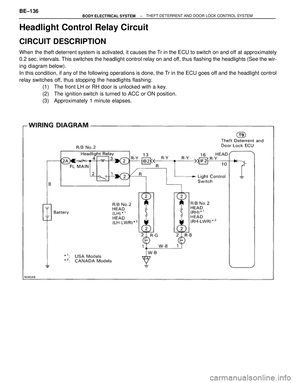
Headlight Control Relay Circuit
CIRCUIT DESCRIPTION
When the theft deterrent system is activated, it causes the Tr in the ECU to switch on and off at approximately
0.2 sec. intervals. This switches the headlight control relay on and off, thus flashing the headlights (See the wir-
ing diagram below).
In this condition, if any of the following operations is done, the Tr in the ECU goes off and the headlight control
relay switches off, thus stopping the headlights flashing:
(1) The front LH or RH door is unlocked with a key.
(2) The ignition switch is turned to ACC or ON position.
(3) Approximately 1 minute elapses.
BE±136± BODY ELECTRICAL SYSTEMTHEFT DETERRENT AND DOOR LOCK CONTROL SYSTEM
Page 739 of 2543
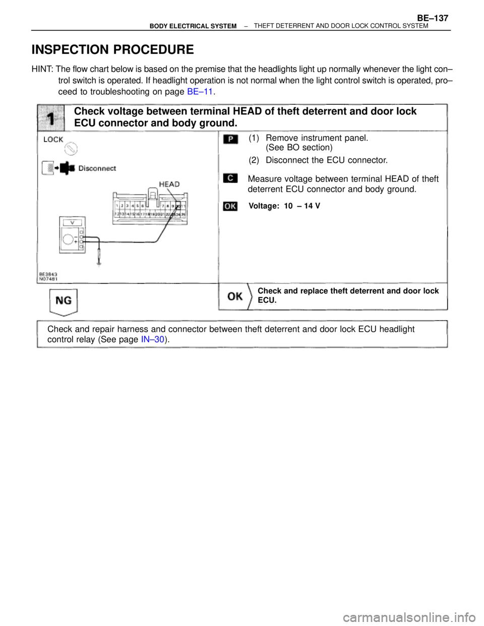
INSPECTION PROCEDURE
HINT: The flow chart below is based on the premise that the headlights light up normally whenever the light con±
trol switch is operated. If headlight operation is not normal when the light control switch is operated, pro±
ceed to troubleshooting on page BE±11.
Check and replace theft deterrent and door lock
ECU.
Measure voltage between terminal HEAD of theft
deterrent ECU connector and body ground.
Voltage: 10 ± 14 V
Check and repair harness and connector between theft deterrent and door lock ECU headlight
control relay (See page IN±30).
Check voltage between terminal HEAD of theft deterrent and door lock
ECU connector and body ground.
(1) Remove instrument panel.
(See BO section)
(2) Disconnect the ECU connector.
± BODY ELECTRICAL SYSTEMBE±137THEFT DETERRENT AND DOOR LOCK CONTROL SYSTEM
Page 740 of 2543
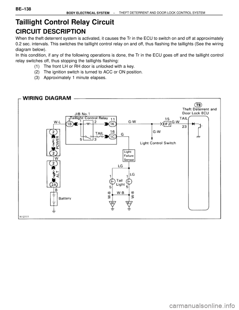
Taillight Control Relay Circuit
CIRCUIT DESCRIPTION
When the theft deterrent system is activated, it causes the Tr in the ECU to switch on and off at approximately
0.2 sec. intervals. This switches the taillight control relay on and off, thus flashing the taillights (See the wiring
diagram below).
In this condition, if any of the following operations is done, the Tr in the ECU goes off and the taillight control
relay switches off, thus stopping the taillights flashing:
(1) The front LH or RH door is unlocked with a key.
(2) The ignition switch is turned to ACC or ON position.
(3) Approximately 1 minute elapses.
BE±138± BODY ELECTRICAL SYSTEMTHEFT DETERRENT AND DOOR LOCK CONTROL SYSTEM
Page 741 of 2543
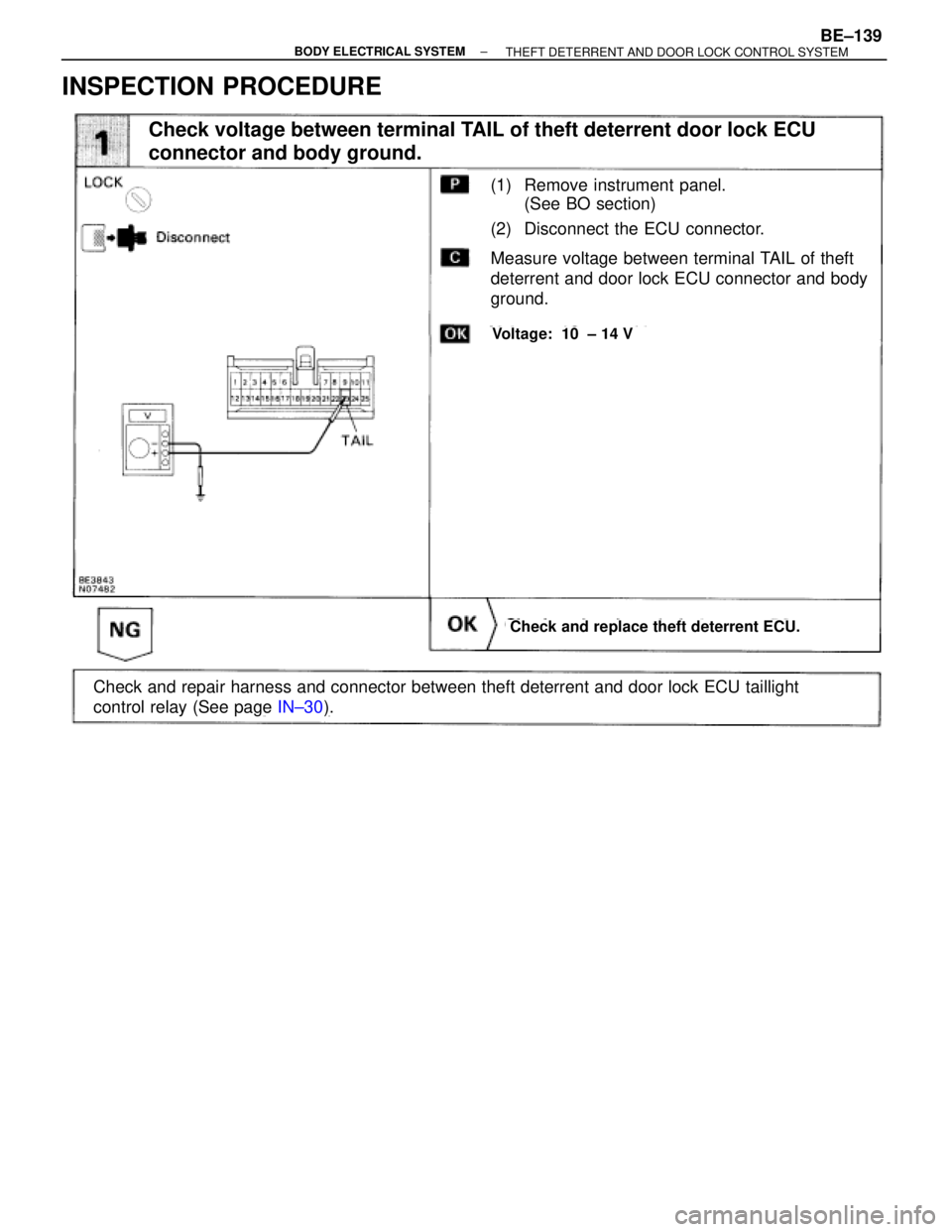
INSPECTION PROCEDURE
(See page IN±30).
(1) Remove instrument panel.
(See BO section)
(2) Disconnect the ECU connector.
Check and replace theft deterrent ECU.
Measure voltage between terminal TAIL of theft
deterrent and door lock ECU connector and body
ground.
Voltage: 10 ± 14 V
Check and repair harness and connector between theft deterrent and door lock ECU taillight
control relay (See page IN±30).
Check voltage between terminal TAIL of theft deterrent door lock ECU
connector and body ground.
± BODY ELECTRICAL SYSTEMBE±139THEFT DETERRENT AND DOOR LOCK CONTROL SYSTEM
Page 803 of 2543
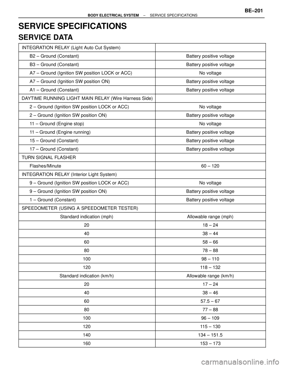
SERVICE SPECIFICATIONS
SERVICE DATA
�������������������� �������������������� INTEGRATION RELAY (Light Auto Cut System)����������������� �����������������
�������������������� �������������������� B2 ± Ground (Constant)����������������� �����������������Battery positive voltage
�������������������� �������������������� B3 ± Ground (Constant)����������������� �����������������Battery positive voltage
�������������������� �������������������� A7 ± Ground (Ignition SW position LOCK or ACC)����������������� �����������������No voltage�������������������� �
������������������� A7 ± Ground (Ignition SW position ON)
����������������� �
����������������Battery positive voltage�������������������� �
������������������� �������������������� A1 ± Ground (Constant)
����������������� �
���������������� �����������������Battery positive voltage
�������������������� �������������������� DAYTIME RUNNING LIGHT MAIN RELAY (Wire Harness Side)����������������� �����������������
�������������������� �������������������� 2 ± Ground (Ignition SW position LOCK or ACC)����������������� �����������������No voltage
�������������������� �������������������� 2 ± Ground (Ignition SW position ON)����������������� �����������������Battery positive voltage�������������������� �������������������� 11 ± Ground (Engine stop)����������������� �����������������No voltage�������������������� �
������������������� �������������������� 11 ± Ground (Engine running)
����������������� �
���������������� �����������������Battery positive voltage
�������������������� �������������������� 15 ± Ground (Constant)����������������� �����������������Battery positive voltage
�������������������� �������������������� 17 ± Ground (Constant)����������������� �����������������Battery positive voltage
�������������������� �������������������� TURN SIGNAL FLASHER����������������� �����������������
�������������������� �������������������� Flashes/Minute����������������� �����������������60 ± 120�������������������� �
������������������� �������������������� INTEGRATION RELAY (Interior Light System)
����������������� �
���������������� �����������������
�������������������� �������������������� 9 ± Ground (Ignition SW position LOCK or ACC)����������������� �����������������No voltage
�������������������� �������������������� 9 ± Ground (Ignition SW position ON)����������������� �����������������Battery positive voltage
�������������������� �������������������� 1 ± Ground (Constant)����������������� �����������������Battery positive voltage
�������������������� �������������������� SPEEDOMETER (USING A SPEEDOMETER TESTER)����������������� �����������������
�������������������� �
�������������������Standard indication (mph)
����������������� �
����������������Allowable range (mph)�������������������� �
������������������� ��������������������20
����������������� �
���������������� �����������������18 ± 24
�������������������� ��������������������40����������������� �����������������38 ± 44
�������������������� ��������������������60����������������� �����������������58 ± 66
�������������������� ��������������������80����������������� �����������������78 ± 88�������������������� ��������������������100����������������� �����������������98 ± 110�������������������� �
������������������� ��������������������120
����������������� �
���������������� �����������������118 ± 132
�������������������� ��������������������Standard indication (km/h)����������������� �����������������Allowable range (km/h)
�������������������� ��������������������20����������������� �����������������17 ± 24
�������������������� ��������������������40����������������� �����������������38 ± 46
�������������������� ��������������������60����������������� �����������������57.5 ± 67�������������������� �
������������������� ��������������������80
����������������� �
���������������� �����������������77 ± 88
�������������������� ��������������������100����������������� �����������������96 ± 109
�������������������� ��������������������120����������������� �����������������115 ± 130
�������������������� ��������������������140����������������� �����������������134 ± 151.5
�������������������� ��������������������160����������������� �����������������153 ± 173
± BODY ELECTRICAL SYSTEMSERVICE SPECIFICATIONSBE±201