Page 351 of 2543

A340E(Others) AUTOMATIC TRANSMISSIONUPPER VALVE BODY - A340E(Others) AUTOMATIC TRANSMISSIONUPPER VALVE BODY -
AT-94
VALVE BODY SPRING SPECIFICATIONS
HINT: During reassembly please refer to the spring specifications below to help you to identify the differ-
ent springs.
MarkName (color)Free length / Outer diameter
mm (in.)Total No. of coils
(A)Down-shift plug (Yellow)27.3 (1.075) / 8.7 (0.343)12.5
(B)Throttle valve (Blue)
(White)20.6 (0.811) / 9.2 (0.362)
or 23.3 (0.917) / 9.2 (0.362)9.5
9.5
(C)3-4 shift valve (Purple)30.8 (1.213) / 9.7 (0.382)10.5
(D)SUPRA, PREVIA
Second coast modulator valve (Orange)24.6 (0.967) / 8.3 (0.327)9.0
(D)OTHERS
Second coast modulator valve (Orange)25.3 (0.996) / 8.6 (0.339)9.5
(E)Lock-up relay valve (Light Gray)21.4 (0.843) / 5.5 (0.217)17.5
(F)Secondary regulator valve (Blue)30.9 (1.217) / 11.2 (0.441)10.5
(G)Cut-back valve (Red)21.8 (0.858) / 6.0 (0.236)13.5
(H)2-3 Shift valve (Blue)30.8 (1.213) / 9.7 (0.382)10.5
(I)SUPRA, PREVIA
Low coast modulator valve (Yellow)26.4 (1.039) / 8.3 (0.327)10.5
(I)OTHERS
Low coast modulator valve (Yellow)30.4 (1.197) / 8.3 (0.327)8.5
AT06D-04
Page 352 of 2543
A340E(Others) AUTOMATIC TRANSMISSIONUPPER VALVE BODY -
AT-95
RETAINERS, PIN, STOPPER, CHECK BALLS AND STRAINER LOCATION
1. RETAINER, STOPPER AND PIN
MarkRetainerHeight / Width / Thickness
mm (in.)
(A)Low coast modulator valve14.5 (0.571) / 5.0 (0.197) / 3.2 (0.126)
(B)2-3 shift valve14.0 (0.551) / 5.0 (0.197) / 3.2 (0.126)
(C)Cut-back valve15.0 (0.591) / 5.0 (0.197) / 3.2 (0.126)
(D)Secondary regulator valve14.0 (0.551) / 5.0 (0.197) / 3.2 (0.126)
(E)Lock-up relay valve21.2 (0.835) / 5.0 (0.197) / 3.2 (0.126)
(F)3-4 shift valve16.5 (0.650) / 6.0 (0.236) / 3.2 (0.126)
(G)2nd coast modulator valve16.5 (0.650) / 6.0 (0.236) / 3.2 (0.126)
AT06E-05
Page 394 of 2543

FUNCTION OF ECU
w Control of Shifting Timing
The ECM has programmed into its memory the optimum shift pattern for each shift lever position (D, 2, L
position) and driving mode (Normal or Manual).
Based on the appropriate shift pattern, the ECM turns No.1 and No.2 solenoid valves on or off in accor-
dance with the vehicle speed signal from the vehicle speed sensor and the throttle opening signal from the
throttle position sensor. In this manner, the ECM operates each shift valve, opening or closing the fluid pas-
sages to the clutches and brakes to permit up±shift or down±shift of the transmission.
HINT: The electronic control system provides shift timing and lock±up control only while the vehicle is travel-
ing forward. In REVERSE, PARK, and NEUTRAL, the transmission is mechanically, not electronically con-
trolled.
w Control of Overdrive
Driving in overdrive is possible if the O/D main switch is on and the shift lever is in the D position. However,
when the vehicle is being driven using the cruise control system (CCS), if the actual vehicle speed drops
to about 4 km/h (2 mph) below the set speed while the vehicle is running in overdrive, the CCS ECU sends
a signal to the ECM to release the overdrive and prevent the transmission from shifting back into overdrive
until the actual vehicle speed reaches the speed set in the CCS memory.
On this model, if the engine coolant temperature falls below 60°C (140°F), the ECM sends a signal to the
ECM, preventing the transmission from up±shifting into overdrive.
w Control of Lock±Up System
The ECM has programmed in its memory a lock±up clutch operation pattern for each driving mode (Normal
of Manual). Based on this lock±up pattern, the ECM turns lock±up solenoid valve on or off in accordance
with the vehicle speed signals received from the vehicle speed sensor and the throttle opening signals from
the throttle position sensor.
Depending on whether lock±up solenoid valve is on or off, the lock±up relay valve performs changeover
of the fluid passages for the converter pressure acting on the torque converter clutch to engage or disen-
gage the lock±up clutch.
Mandatory Cancellation of Lock±Up System:
If any of the following conditions exist, the ECM turns off lock±up solenoid valve to disengage the lock±up
clutch.
1) The brake light switch comes on (during braking).
2) The IDL points of the throttle position sensor close (throttle valve fully closed).
3) The vehicle speed drops 4 km/h (2 mph) or more below the set speed while the cruise control system
is operating.
4) The engine coolant temperature falls below 60°C (140°F) and vehicle speed is under 60 km/h (37
mph), or 35°C (95°F) and vehicle speed is under 40 km/h (25 mph).
The purpose of 1) and 2) above is to prevent the engine from stalling if the rear wheels lock up.
The purpose of 3) is to cause the torque converter clutch to operate to obtain torque multiplication. The
purpose of 4) is both to improve general driveability, and to speed up transmission warm±up.
Also, while the lock±up system is in operation, the ECM will temporarily turn it off during up±shift or down±
shift in order to decrease shifting shock. AT1±8
± AT340E (2JZ±GE) AUTOMATIC TRANSMISSIONOPERATION
Page 447 of 2543
AT1±62
3±4 shift valveLow coast
modulator valveB2 accumulator
C2 accumulatorCut±back valveLock±up relay valvePrimary regulator
valveAccumulatorcontrol valve2nd coast
modulator valvePressure relief
valveOFF±Vehicle repair
matrix chartB0 accumulatorC0 accumulator
± AT340E (2JZ±GE) AUTOMATIC TRANSMISSIONTROUBLESHOOTINGAT1±61
Page 461 of 2543

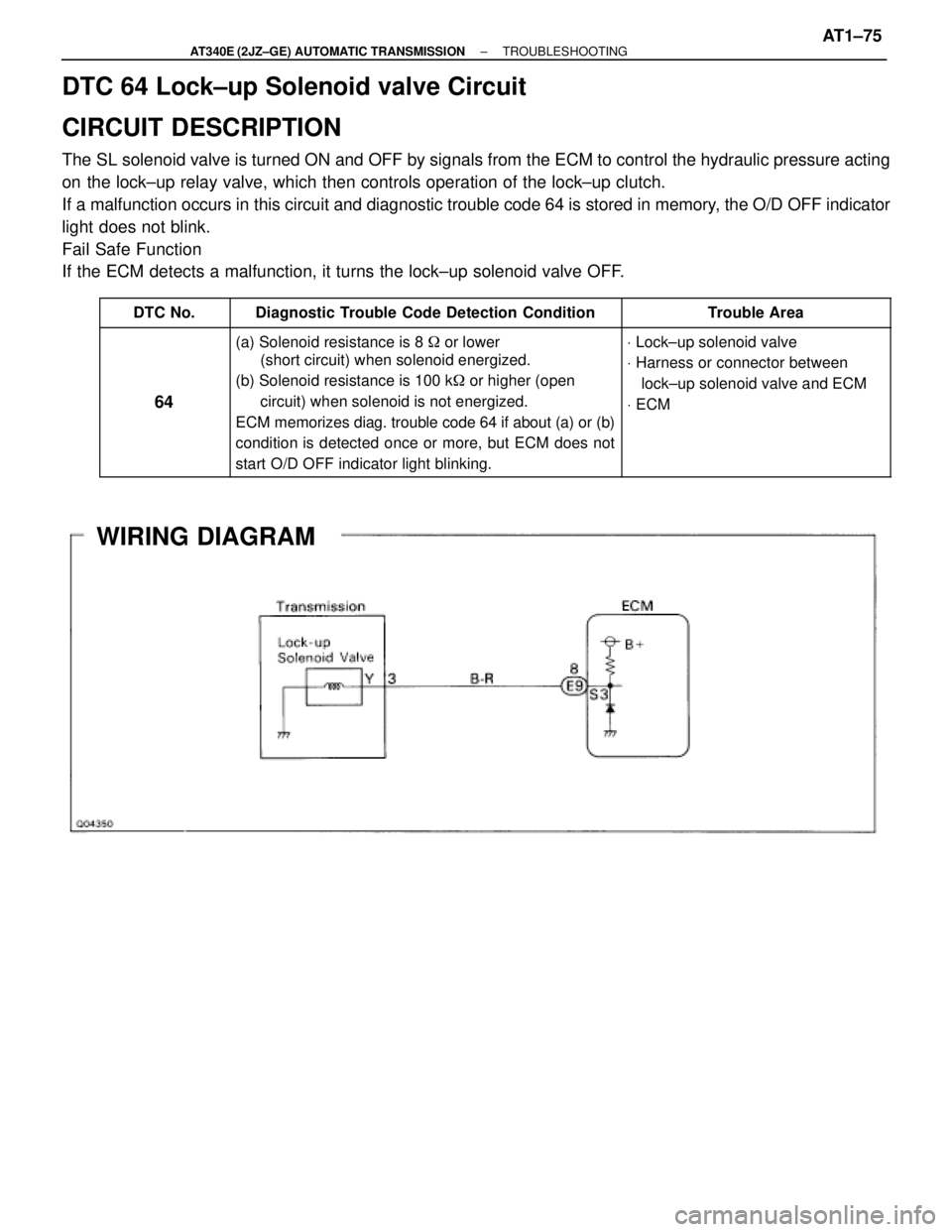
DTC 64 Lock±up Solenoid valve Circuit
CIRCUIT DESCRIPTION
The SL solenoid valve is turned ON and OFF by signals from the ECM to control the hydraulic pressure acting
on the lock±up relay valve, which then controls operation of the lock±up clutch.
If a malfunction occurs in this circuit and diagnostic trouble code 64 is stored in memory, the O/D OFF indicator
light does not blink.
Fail Safe Function
If the ECM detects a malfunction, it turns the lock±up solenoid valve OFF.
������ ������DTC No.����������������� �����������������Diagnostic Trouble Code Detection Condition������������ ������������Trouble Area
������ �
����� �
����� �
����� �
����� �
����� ������
64
����������������� �
���������������� �
���������������� �
���������������� �
���������������� �
���������������� �����������������
(a) Solenoid resistance is 8 � or lower
(short circuit) when solenoid energized.
(b) Solenoid resistance is 100 k� or higher (open
circuit) when solenoid is not energized.
ECM memorizes diag. trouble code 64 if about (a) or (b)
condition is detected once or more, but ECM does not
start O/D OFF indicator light blinking.������������
������������
������������
������������
������������
������������ ������������
V Lock±up solenoid valve
V Harness or connector between
lock±up solenoid valve and ECM
V ECM
WIRING DIAGRAM
± AT340E (2JZ±GE) AUTOMATIC TRANSMISSIONTROUBLESHOOTINGAT1±75
Page 551 of 2543
3±4 shift valveLock±up control
valveLock±up relay
valveAccumulator
control valveSolenoidmodulator
valve
C1 accumulator
Orifice control
valveSolenoid relay
valveC2 accumulatorLow coast
modulator valveB2 accumulator2nd coast
modulator valvePressure relief
valveOFF±Vehicle repair
matrix chartB0 accumulatorC0 accumulator
± A340E (2JZÐGTE) AUTOMATIC TRANSMISSIONTROUBLESHOOTINGAT2±67
Page 605 of 2543

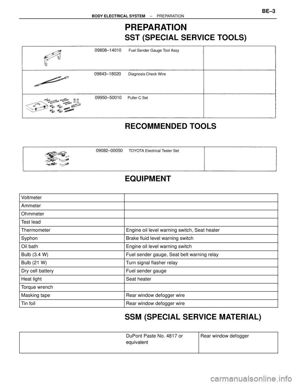
PREPARATION
SST (SPECIAL SERVICE TOOLS)
09843±18020Diagnosis Check Wire
09808±14010Fuel Sender Gauge Tool Assy
09950±50010Puller C Set
RECOMMENDED TOOLS
09082±00050TOYOTA Electrical Tester Set
�
EQUIPMENT
��������������� �
�������������� ���������������Voltmeter
���������������������� �
��������������������� ����������������������
��������������� ���������������Ammeter���������������������� ����������������������
��������������� ���������������Ohmmeter���������������������� ����������������������
��������������� ���������������Test lead���������������������� ����������������������
��������������� ���������������Thermometer���������������������� ����������������������Engine oil level warning switch, Seat heater
��������������� ���������������Syphon���������������������� ����������������������Brake fluid level warning switch
��������������� ���������������Oil bath���������������������� ����������������������Engine oil level warning switch
��������������� ���������������Bulb (3.4 W)���������������������� ����������������������Fuel sender gauge, Seat belt warning relay��������������� ���������������Bulb (21 W)���������������������� ����������������������Turn signal flasher relay��������������� ���������������Dry cell battery���������������������� ����������������������Fuel sender gauge��������������� �
�������������� ���������������Heat light
���������������������� �
��������������������� ����������������������Seat heater
��������������� ���������������Torque wrench���������������������� ����������������������
��������������� ���������������Masking tape���������������������� ����������������������Rear window defogger wire
��������������� ���������������Tin foil���������������������� ����������������������Rear window defogger wire
SSM (SPECIAL SERVICE MATERIAL)
������������������������� �
������������������������
DuPont Paste No. 4817 or
equivalent
������������ �
�����������
Rear window defogger
������������������������� �
������������������������ �������������������������
equivalent������������ �
����������� ������������
± BODY ELECTRICAL SYSTEMPREPARATIONBE±3
Page 611 of 2543
KEY UNLOCK WARNING INSPECTION
1. INSPECT INTEGRATION RELAY OPERATION
(a) Connect the positive (+) lead from the battery to terminal 1,
the negative (±) lead to terminals 5 and 10.
(b) Check that the buzzer sounds when the negative (±) lead
from the battery is connected to terminal 6.
If operation is not as specified, replace the relay.
2. INSPECT RELAY CIRCUIT
See page BE±18
± BODY ELECTRICAL SYSTEMIGNITION SWITCHBE±9