Page 956 of 2543
If the same code is still output after the diagnostic trouble code is deleted, check the contact
condition of each connection.
If the connections are normal, the ECU may be defective.
Check TRAC actuator solenoid.
Disconnect TRAC actuator connector.
Check continuity between each terminal of TRAC
solenoid relay shown below.
Open
Continuity
(Reference value �� �)Terminals 2 and 4
Terminals 1 and 2
Repair or replace harness or connector.
Check for short in harness and connector between SMC and SRC terminals
with TRAC actuator and ECU connectors are disconnected.
Terminals 1 and 3
Repair or replace harness or connector.
Replace TRAC actuator.
Check for open and short in harness and connector between solenoid relay
and ECU (See page
IN±30).
`
± BRAKE SYSTEMANTI±LOCK BRAKE SYSTEM (ABS)BR±87
Page 957 of 2543

CIRCUIT DESCRIPTION
The speed sensor detects the wheel speed and sends the ap-
propriate signals to the ECU. These signals are used to control
both the ABS and TRAC control systems. The front and rear ro-
tors each have 48 serrations. When the rotors rotate, the mag-
netic field emitted by the permanent magnet in the speed sensor
generates an AC voltage. Since the frequency of this AC volt-
age changes in the direct proportion to the speed of the rotor,
the frequency is used by the ECU to detect the speed of each
wheel.
31, 32
33, 34
35
36
Detection of any of conditions (1) through (3):
(1) At vehicle speed of 10 km/h (6 mph) or
more, pulses are not input for 5 sec.
(2) Momentary interruption of he vehicle
speed sensor signal occurs at least 7
times in the time between switching the
ignition switch ON and switching it OFF.
(3) Abnormal fluctuation of speed sensor sig±
nals with the vehicle speed 20 km/H (12
mph) or more.
Speed sensor signal is not input for about 1
sec. while the left front and right rear speed
sensor signals are being checked with the IG
switch ON.
Speed sensor signal is not input for about 1
sec. while the right front and left rear speed
sensor signals are being checked with the IG
switch ON.
� Right front, left front, right rear and left rear
speed sensor.
� Open or short in each speed sensor circuit.
� ECU
� Open in left front, right rear speed sensor
circuit.
� ECU
� Open in right front, left rear speed sensor
circuit.
�ECU
HINT: DTC No.31 is for the right front speed sensor.
DTC No. 32 is for the left front speed sensor.
DTC No.33 is for the right rear speed sensor.
DTC No.34 is for the left rear speed sensor.
Fail safe function: If trouble occurs in the speed sensor circuit, the ECU cuts off current to the ABS
solenoid relay and prohibits ABS control.
DTC 31 32 33 34 35 36 Speed Sensor Circuit
BR±88± BRAKE SYSTEMANTI±LOCK BRAKE SYSTEM (ABS)
Page 961 of 2543

DTC 41 IG Power Source Circuit
CIRCUIT DESCRIPTION
This is the power source for the ECU, hence the CPU and the actuators.
�������� ��������DTC No.���������������� ����������������Diagnostic Trouble Code Detecting Condition`�������������� ��������������Trouble area�������� �
������� �
������� �
������� �
������� �
������� �
������� ��������
41
���������������� �
��������������� �
��������������� �
��������������� �
��������������� �
��������������� �
��������������� ����������������
When either of the following (1) or (2) is
detected:
(1) Voltage at ECU terminal IG1 is less than
9.5 V for more than 10 sec. while vehicle
speed is 3 km/h (1.9 mph) or more.
(2) Voltage at ECU terminal IG1 is more than
17 V for more than 1.2 sec.
�������������� �
������������� �
������������� �
������������� �
������������� �
������������� �
������������� ��������������
� Battery
� IC regulator
� Open or short in power source circuit
� ECU
Fail safe function: If trouble occurs in the power source circuit, the ECU cuts off current to the ABS solenoid relay
and prohibits ABS control.
BR±92± BRAKE SYSTEMANTI±LOCK BRAKE SYSTEM (ABS)
Page 966 of 2543
DTC 51 ABS Pump Motor Lock
CIRCUIT DESCRIPTION
������� �
������ �������DTC No.
�������������������� �
������������������� ��������������������Diagnostic Trouble Code Detecting Condition
����������� �
���������� �����������Trouble area
������� �
������ �������51�������������������� �
������������������� ��������������������
Pump motor is not operating normally during
initial check.����������� �
���������� ����������� � ABS pump motor
Fail safe function: If trouble occurs in the ABS pump motor, the ECU cuts off the current to the solenoid relay
and prohibits ABS control.
WIRING DIAGRAM
See page BR±72
INSPECTION PROCEDURE
See inspection of ABS actuator (See page BR±44).
± BRAKE SYSTEMANTI±LOCK BRAKE SYSTEM (ABS)BR±97
Page 967 of 2543
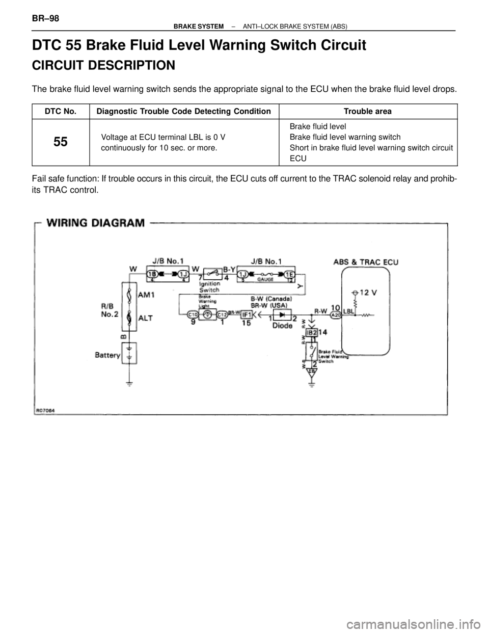
DTC 55 Brake Fluid Level Warning Switch Circuit
CIRCUIT DESCRIPTION
The brake fluid level warning switch sends the appropriate signal to the ECU when the brake fluid level drops.
������ ������DTC No.���������������� ����������������Diagnostic Trouble Code Detecting Condition���������������� ����������������Trouble area
������ �
����� �
����� �
����� ������
55
���������������� �
��������������� �
��������������� �
��������������� ����������������
Voltage at ECU terminal LBL is 0 V
continuously for 10 sec. or more.
���������������� �
��������������� �
��������������� �
��������������� ����������������
� Brake fluid level
� Brake fluid level warning switch
� Short in brake fluid level warning switch circuit
� ECU
Fail safe function: If trouble occurs in this circuit, the ECU cuts off current to the TRAC solenoid relay and prohib-
its TRAC control. BR±98
± BRAKE SYSTEMANTI±LOCK BRAKE SYSTEM (ABS)
Page 969 of 2543
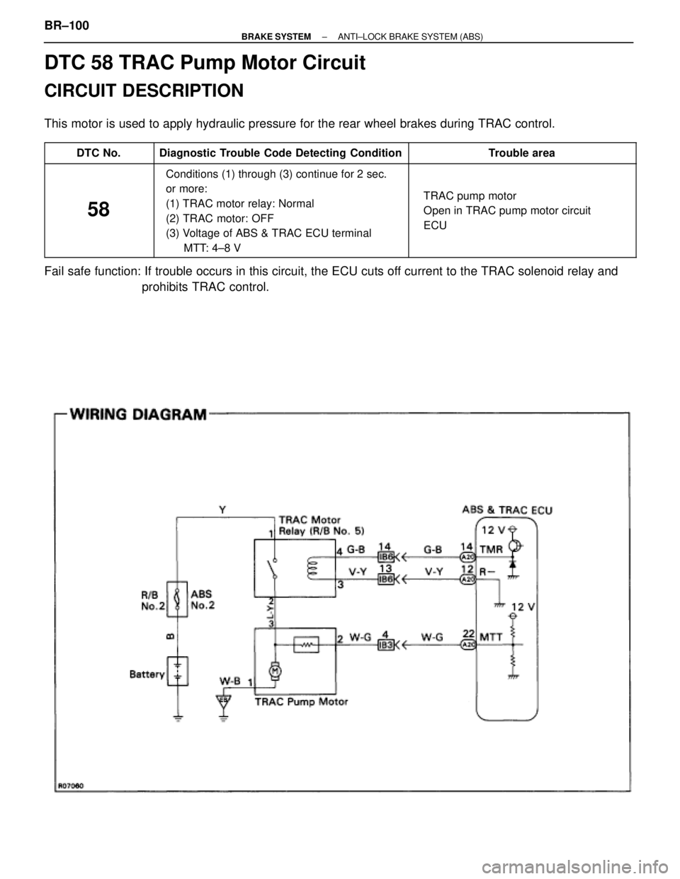
DTC 58 TRAC Pump Motor Circuit
CIRCUIT DESCRIPTION
This motor is used to apply hydraulic pressure for the rear wheel brakes during TRAC control.
������� �������DTC No.��������������� ���������������Diagnostic Trouble Code Detecting Condition��������������� ���������������Trouble area
������� �
������
�������
�������
�������
�������
�������
58
���������������
���������������
���������������
���������������
���������������
��������������� ���������������
Conditions (1) through (3) continue for 2 sec.
or more:
(1) TRAC motor relay: Normal
(2) TRAC motor: OFF
(3) Voltage of ABS & TRAC ECU terminal
MTT: 4±8 V��������������� �
�������������� �
�������������� �
�������������� �
�������������� �
�������������� ���������������
� TRAC pump motor
� Open in TRAC pump motor circuit
� ECU
Fail safe function: If trouble occurs in this circuit, the ECU cuts off current to the TRAC solenoid relay and
prohibits TRAC control.
BR±100± BRAKE SYSTEMANTI±LOCK BRAKE SYSTEM (ABS)
Page 977 of 2543

Check ABS warning light.
Disconnect the connectors from solenoid relay.
Check continuity between each terminal of ABS
solenoid relay shown below.
Replace bulb or combination meter assembly.
See Combination Meter Troubleshooting on page BE±43.
(1) Apply battery positive voltage between termi-
nals (A9) 1 and (A8) 3.
(2) Check continuity between each terminal of
ABS solenoid relay shown below.
Connect the � test lead to terminal (A9)4 and the
� lead to the terminal (A9)5. Check continuity be-
tween the terminals.
Continuity
If there is no continuity, connect the � test lead to
terminal (A9)4 and the � lead to terminal (A9)5.
Recheck continuity between terminals.
Terminals (A9) 5 and (A9) 6
Terminals (A9) 2 and (A9) 5
Open
Continuity
Continuity
Open
Terminals (A9) 1 and (A8) 3
Terminals (A9) 5 and (A9) 6
Terminals (A9) 2 and (A9) 5
Continuity
(Reference value 80 �)
Replace ABS control relay.
Check ABS solenoid relay.
Repair or replace and check for open in harness and connector between DLC1 and ABS solenoid
relay and body ground (See page IN±30).Repair or replace and check for open in harness and connector between DLC1 and ABS solenoid
relay and body ground (See page IN±30).
INSPECTION PROCEDURE (w/o TRAC)
Perform troubleshooting in accordance with the chart below for each trouble symptom.
��������������� �
��������������
���������������
ABS warning light does not light up
�������� �
������� ��������Go to step [1]
��������������� �
��������������
���������������
ABS warning light remains on�������� �
������� ��������Go to step [3]
BR±108± BRAKE SYSTEMANTI±LOCK BRAKE SYSTEM (ABS)
Page 978 of 2543
Is diagnostic trouble code output?
Repair circuit indicated by the code output.
Do diagnostic trouble code check on page BR±54.
Does ABS warning light go off if short pin is removed?
Check ABS solenoid relay (See step No.2).
Repair ABS control relay.
Check for short in harness and connector be-
tween warning light and DLC1 and ECU (See
page IN±30).
Repair or replace and check for short in harness
and connector between DLC1 and ABS solenoid
relay (See page IN±30).
± BRAKE SYSTEMANTI±LOCK BRAKE SYSTEM (ABS)BR±109